CNT-SVX11A-EN 7
Controller Features
Each Tracer ZN524 unit controller circuit
board is equipped with enhancements
to help facilitate service, testing, and
diagnosis.
Each board has:
• Manual test button,
• Status LED,
• Communication status LED,
• Service button,
• Quick terminal connectors, and
• Easy to read screen printing. (See
Figure 2: Page 6).
Service
The Trane Tracer ZN524 unit controller is
serviced using Rover®, the software
service tool. Rover is designed to sup-
port the Tracer ZN524 unit controller on
a single or dual compressor water-
source heat pump.
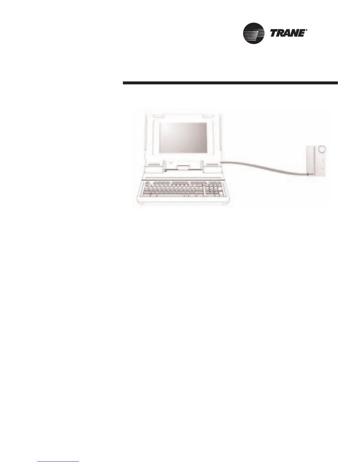
For “remote” access to the communi-
cating units, the zone sensors offered
with the Tracer ZN524 have a telephone
style (RJ-11) connector allowing field
connection between Rover and the zone
sensor; however, the RJ-11 connector
must be connected to the communica-
tions terminals on the Tracer ZN524 unit
controller.(See Figure 3: “Rover service
tool connected to the RJ-11 communi-
cation jack in a zone sensor”)
The zone sensor may also be used
when trying to locate a unit. By press-
ing the on button on the zone sensor
for 5 seconds or using the “wink” com-
mand in Rover, the circuit board
receives the signal causing the status
LED to “wink.” Winking allows visual
identifier on the board for service tech-
nicians.
The Tracer ZN524 also includes features
such as a test output to manually test
all of the end devices. (See “Manual
Output Test” on page 32, for more infor-
mation.)
Typical Components
A typical water-source heat pump sys-
tem with a DDC package consists of the
following physical components, in addi-
tion to the mechanical equipment:
• Tracer ZN524—contains the sensor
input circuits, service adjustments,
microprocessor control electronics,
and communications hardware. Power
is supplied by a separately mounted
24 VAC transformer.
• Sensor Modules—a variety of analog
sensors that provide temperature and
optional humidity sensing and CO2
sensor; and an operator interface to
the Tracer ZN524 for operating
modes, status, and temperature set
points.
• Standard End Devices—a variety of
devices that help to gather informa-
tion and control capacity are used by
the Tracer ZN524 in its control
algorithm to condition the space to
the desired temperature and relative
humidity level.
Note: The Tracer ZN524 is a config-
ured controller. It will not operate
without a valid downloaded config-
uration file.
The Tracer ZN524 controller supports
ICS and peer-to-peer communications
as well as stand-alone operation. A
number of control features may be con-
figured at the factory or by using the
Rover service tool.
(See “Configuration” on page 20, for
more information.)
Figure 3: Rover service tool connected to the RJ-11
communication jack in a zone sensor

 Loading...


