36 CNT-SVX11A-EN
Troubleshooting
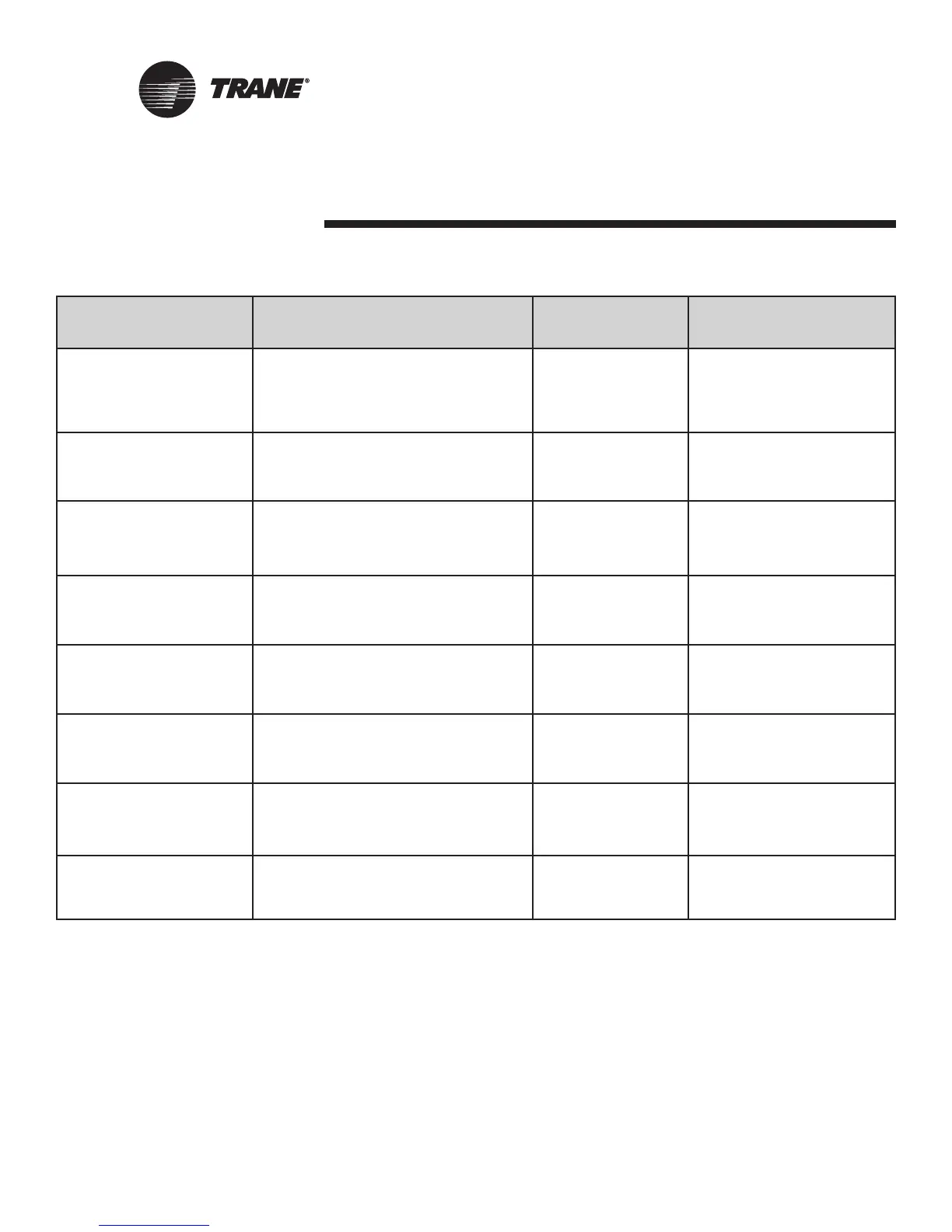
Diagnostic Unit Response Latching/ Reset
non-latching
Fan—enabled
Valves—enabled
Humidity Input Failure
3
Compressor—enabled Non-latching Communicated or manual reset
Reheat—disabled
CO2 Sensor Fan—enabled
Failure
3
Valves—enabled Non-latching Communicated or manual reset
Compressor—enabled
Generic
AIP No Unit Reaction Non-latching Communicated or manual reset
Failure
3
Maintenance Fan—enabled
Required Valves—enabled Non-latching Communicated or manual reset
Compressor—enabled
Local Fan—enabled
Fan Mode Valves—enabled Non-latching Communicated or manual reset
Failure
3
Compressor—enabled
Local Fan—enabled
Setpoint Valves—enabled Non-latching Communicated or manual reset
Failure
3
Outdoor air damper—enabled
Invalid Fan—disabled
Unit Valves—disabled Latching Communicated or manual reset
Configuration
2
Compressor—disabled
Fans—enabled
Normal Valves—enabled Non-latching N/A
Compressor—enabled
Table 19: Tracer ZN524 Unit Controller diagnostics - continued
1: The generic binary output (TB4-1, TB4-2) state is unaffected by all unit diagnostics.
2: During manual output test, these diagnostics make the green status LED flash in a two-blink pattern. For more information see, Manual
Output Test, on page 32.
3: These diagnostics are non-latching and automatically reset when the input is present and valid.

 Loading...


