CNT-SVX11A-EN 33
Troubleshooting
If a two-blink pattern remains after an
attempt to clear diagnostics, the diag-
nostic condition is still present and may
affect the manual output test. The diag-
nostic must then be cleared using
another method. (See “Resetting
Diagnostics” on page 35 for more
information.)
Test Procedure
The procedure for testing is:
1. Press and hold the Test button for at
least two seconds, then release the
button to start the test mode.
2. When manual output test mode
begins, the controller turns off all out
puts and calibrates end devices
closed.
3. Press the Test button once to advance
through each step of the test
sequence.
Note: To help ensure accurate
testing do not press the test
button more than once per second.
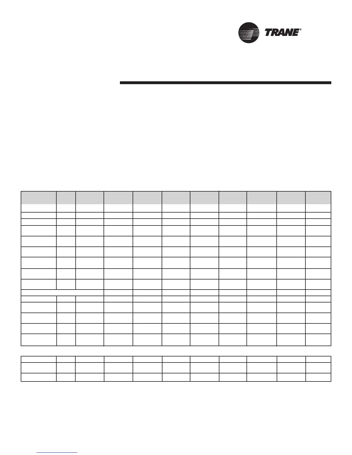
Alternatively, the manual output test
can be controlled over the communica-
tions network by using Rover. When
conducting the manual output test via
communications network, the sequence
must start with Step 1 (
OFF), as shown
in Table 18.
Step Fan Reversing Elec. Heat/ Compressor Compressor Isolation Isolation Water-side Outside Air Generic
Valve Reheat 1 2 Valve 1 Valve 2 Economizer Damper
BO1 BO2 BO3 BO4 BO5 BO6 BO7 BO8 BO9 BO10
1. Off
1
Off Off Off Off Off Off Off Off Off Off
2. Fan
2
On
3. Isolation On On
Valve 1
4. Waterside On On On
Economizer
5. Isolation On On On
Valve 1 & 2
6. Reversing On On On On
Valve
7. 1st Stage On On On On On
Cool
8. 1st & 2nd On On On On On On
Stage Cool
9. Heat Mode:
See Table Below
10.
Compressor
3
On On On
11. 1st Stage On On On On
Heat
12. 2nd Stage On On On On On
Heat
13. Outside
4
On On
Air Damp.
14. Generic
5
On On
Output
1. Upon entering manual output test mode, the controller turns off all fan outputs and drives all dampers and valves closed (if required).
2. At the beginning of Step 2, the controller attempts to clear all diagnostics.
3. This stage helps avoid an abrupt transition from cooling to heating by turning off the compressors prior to changing the reversing valve
state.
4. Binary output 9 (BOP9) will be controlled during this step regardless of its configuration.
5. After the generic output setup, the test sequence performs the exit step. This initiates a reset and attempts to return the controller to
normal operation.
9. Hot Gas On On On On On On
9. No Heat/ On On On On
Boilerless
9. Concurrent On On On On On On
Heat Type
Table 18: Test sequence

 Loading...


