TTV-IOM-R410A 11
Maintenance
Evaporator Fan Motor
Continuity test
Open the unit isolating switch and remove the leads from the
terminals of the motor. Test continuity of the windings by placing
the probes of an ohmeter against each two terminal
combinations. Meter readings should be obtained across any
two of the three terminals and each of the readings should be
approximately equal.
Earthed motor
Place one of the test leads of an insulation tester or megger
against bare metal and another on each of the motor terminals
in turn. The reading obtained should be in the range 2 megohm
to infinity. If the reading is substantially below this range an
earthed winding is indicated.
Unit supply voltage.
Voltage at the unit terminals must be within plus or minus 10%
of the nominal nameplate rating. Measure the voltage while
the motor is starling to determine if the voltage drops below
the minimum value during starting surge. Check voltage at
motor terminals rather than at the isolation switch to detemine
if the main supply, loose terminals or defective wiring is causing
voltage problem
s.
Voltage imbalance
Voltage unbalance on three phase systems can cause motor
overheating and eventual failure.
Maximum allowable imbalance is 2.5%. Voltage imbalance is
defined as the sum of the deviation of the three voltages from
the average without regard to sign, divided by twice the average
voltage, e.g. if the three measured voltages are 380, 398 and
400, the average voltage will be:
Then the percentage imbalance will be
398+400+380 = 393V
3
In this example. 3.2% imbalance is not acceptable and the
local electricity board should be notified to correct it. This much
voltage imbalance could result in as much as 20% current
imbalance and an increase in the motor winding temperature.
This results in decrease motor life.
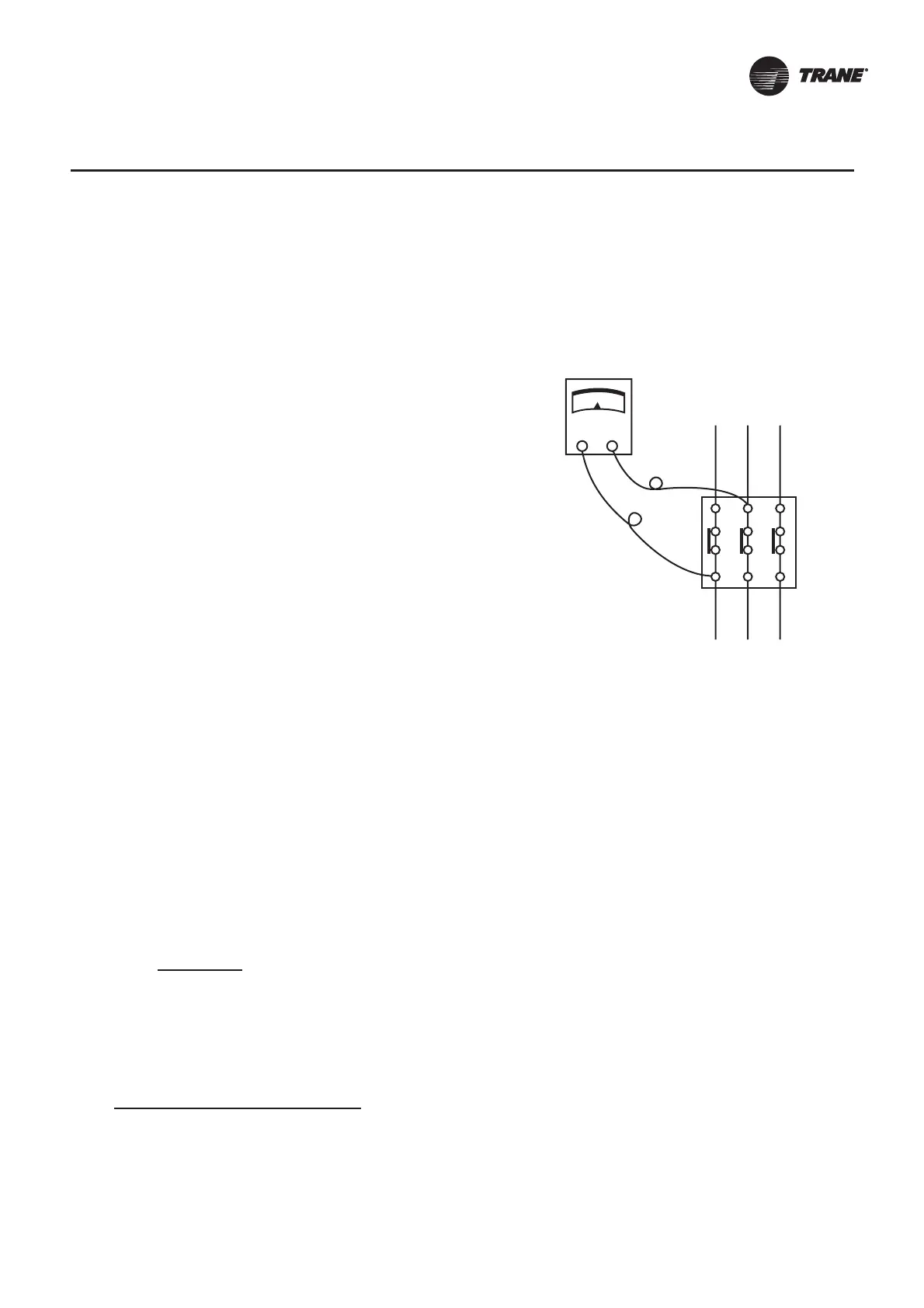
Figure 4 : Contactor test Procedure
Contactor
1. Inspect the contacts. If they appear to be pitted or burned
replace the contactor.
2. Using the ohmmeter, test continuity of the contactor holding
coil. If the coil does not test continuous, replace it.
3. To test the contactor for continuous circuit:
a. Remove the fan motor leads from the contactor.
b. Energise the contactor.
c. Visually note if the contacts are closed or test with a
voltmeter across terminal, 1-4, 1-6 and 3-2 (see figure
4)
4. Test for voltage drop:
a. With the fan motor connected to the contactor, energise
the contactor.
b. Take readings across terminals 1-2, 3-4 and 5-6.
c. A zero voltage reading indicates no voltage drop. If any
reading is obtained, a voltage drop exists and should be
corrected. Inspect the contacts and replace if necessary.
1 3 5
2 4 6
100 x (393-380) + (398-393) + (400-393)
2x393
= 3.2%