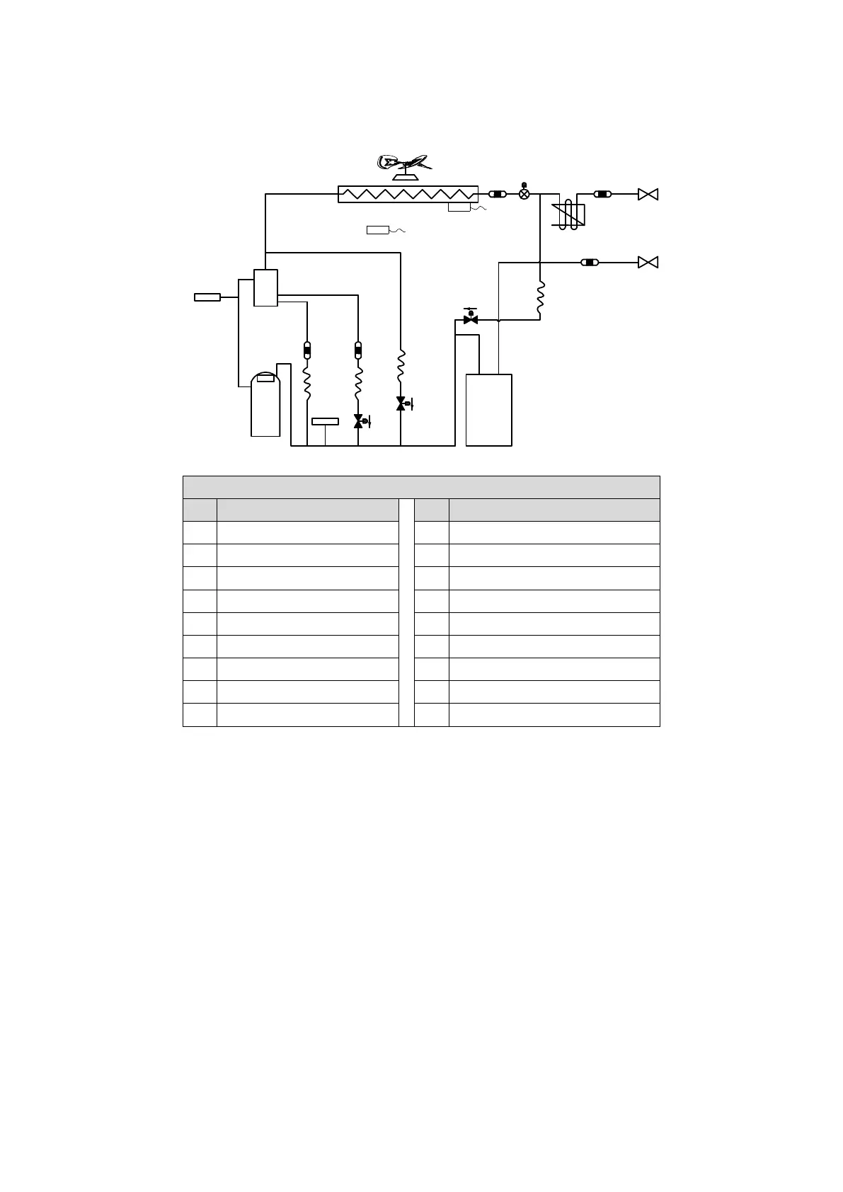
EasyManuals Logo

Trane TVR Pro CO 4TVY0210H8000AA User Manual

Trane TVR Pro CO 4TVY0210H8000AA
118 pages
To Next Page IconTo Next Page
To Previous Page IconTo Previous Page
Page #17 background imageLoading...
Page #17 background image
16
2 Piping Diagrams
8-16HP
Figure 2-2.1: 8-16HP piping diagram
Legend
No. Parts name
No. Parts name
1 Compressor 10 Stop valve (gas side)
2 Discharge temperature sensor 11 Accumulator
3 High pressure sensor 12 Low pressure switch
4 Oil separator 13 Solenoid valve
5 Heat exchanger T3 Heat exchanger temperature sensor
6 Electronic expansion valve (EXV) T4 Outdoor ambient temperature sensor
7 Fan motor SV2 Liquid injection valve
8 Fan SV4 Oil return valve
9 Stop valve (liquid side) SV7 Pressure valve
5
3
4
6
9
10
11
12
2
1
13
13
13
8
7
EXVA
XX
°C
T3
T4
XX
°C
SV4
SV7
SV2

Table of Contents

Questions and Answers:

Question and Answer IconNeed help?

Do you have a question about the Trane TVR Pro CO 4TVY0210H8000AA and is the answer not in the manual?

Trane TVR Pro CO 4TVY0210H8000AA Specifications

General IconGeneral
BrandTrane
ModelTVR Pro CO 4TVY0210H8000AA
CategoryAir Conditioner
LanguageEnglish

Related product manuals