25
2 Stop Operation
The stop operation occurs for one of the three following reasons:
1. Abnormal shutdown: in order to protect the compressors, if an abnormal state occurs the system makes a 'stop with
thermo off' operation and an error code is displayed on the outdoor unit digital displays.
2. The system stops when the set temperature has been reached.
3. A unit stops when the load demanded by the indoor units decreases and can be handled by fewer outdoor units.
3 Startup Control
3.1 Compressor Startup Delay Control
In initial startup control, compressor startup is delayed for 12 minutes in order to let the master unit search for the indoor
units’ addresses. In restart control (except in oil return operation), compressor startup is delayed such that a minimum of 7
minutes has elapsed since the compressor stopped, in order to prevent frequent compressor on/off and to equalize the
pressure within the refrigerant system.
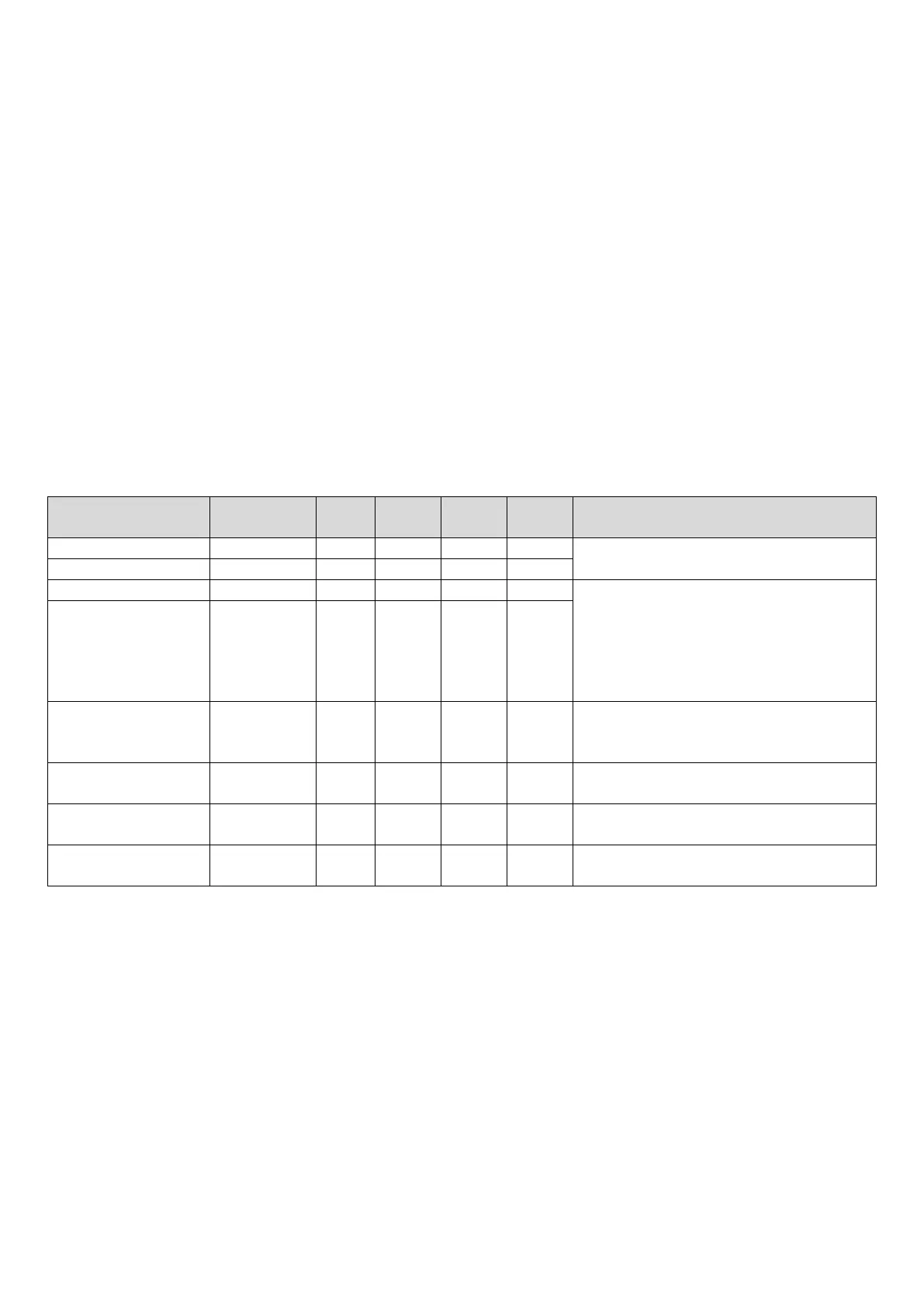
3.2 Startup Control for Cooling Operation
Table 3-3.1: Component control during startup in cooling mode
Component
Wiring diagram
8-12HP 14-16HP 18-22HP 24-30HP Control functions and states
● ● ● ●
Controlled according to load requirement,
operating frequency increased by 1 step / sec
● ●
● ● ● ●
Fan speed controlled according to discharge
pressure (P
c
):
At initial speed for 90 seconds.
Subsequently, P
c
checked every 10 seconds:
P
c
≥ 2.7MPa => 1 step increase.
P
c
≤ 2.1MPa => 1 step decrease.
DC fan motor B FAN2 ● ●
E
valve A
EXVA ● ● ● ●
Position (steps) from 0 (fully closed) to 3000 (fully
open), controlled according to discharge
temperature
Solenoid valve (Liquid
SV2 ● ● ● ● Controlled according to discharge temperature
S
olenoid valve (oil
balance)
SV4 ● ● ● ●
Closed for 200 secs, open for 600 secs
S
olenoid valve
(refrigerant bypass)
SV7 ● ● ● ●
Controlled according to load requirement and
 Loading...