36 UH-SVX01A-EN
Electrical Connections
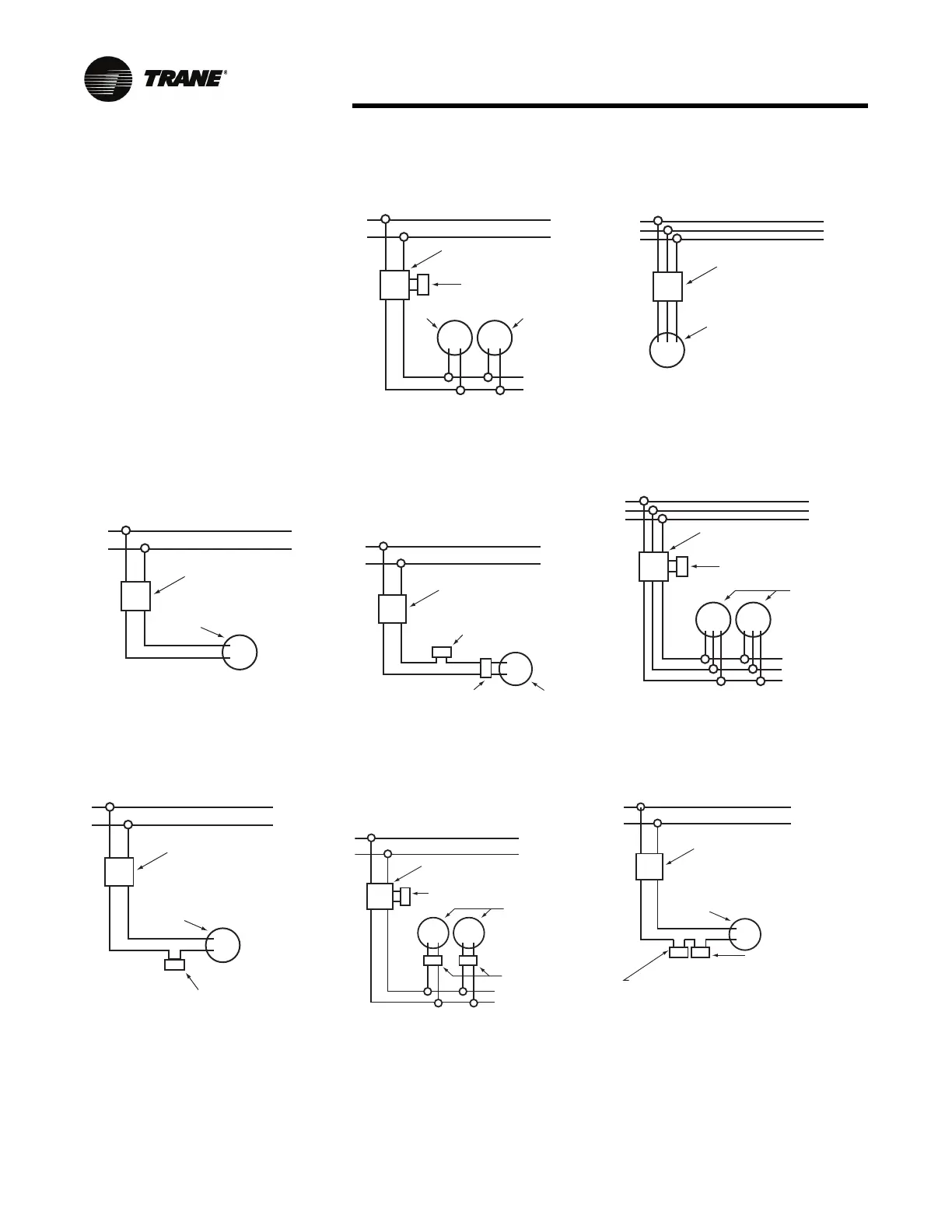
Wiring Installation: S Model
Notice
1. When using a speed controller,
always locate the thermostat
between the speed controller
and the line, not between the
motor and the controller.
2. For internal wiring and overload
p
rotection on all starters, consult
the control manufacturer for
details.
3. When using thermostatic control
with a manual starter, be sure
that the electrical rating of the
thermostat is sufficient to carry
the motor current.
Figure 47.
Figure 48.
MOTOR
MANUAL STARTING
SWITCH
1 PHASE LINE
MANUAL CONTROL WITH
SINGLE PHASE MOTOR
1 PHASE LINE
MOTOR
MANUAL STARTING
SWITCH
ROOM THERMOSTAT
THERMOSTATIC CONTROL
WITH MANUAL STARTER
Figure 49.
Figure 50.
Figure 51.
1 PHASE LINE
MOTOR
MAGNETIC
STARTING SWITCH
THERMOSTAT
MOTOR
THERMOSTATIC CONTROL
USING MAGNETIC STARTER
OPERATING SEVERAL UNITS
1 PHASE LINE
MOTOR
MANUAL STARTING
SWITCH
THERMOSTAT
SPEED CONTROLLER
SPEED CONTROLLER WITH
MANUAL STARTING SWITCH
1 PHASE LINE
MAGNETIC
STARTING SWITCH
THERMOSTAT
MOTORS
SPEED
CONTROLLERS
SPEED CONTROLLERS WITH
MAGNETIC STARTING SWITCH
FOR OPERATING SEVERAL UNITS
Figure 52.
Figure 53.
Figure 54.
MOTOR
MANUAL STARTING
SWITCH
3 PHASE LINE
MANUAL CONTROL WITH
THREE PHASE MOTOR
3 PHASE LINE
MAGNETIC
STARTING SWITCH
THERMOSTAT
THERMOSTATIC CONTROL
OF SEVERAL THREE PHASE UNITS
MOTORS
1 PHASE LINE
MOTOR
MANUAL STARTING
SWITCH
ROOM THERMOSTAT
THERMOSTATIC CONTROL WITH
ACTING LIMIT CONTROLLER
AND MANUAL STARTER
LIMIT CONTROLLER
REVERSE ACTING