VAV-SVX03A-EN 13
Balancing
The following tools are required to
properly adjust and calibrate the
electronic controls:
Digital voltmeter
0 to 2 in. wg magnehelic gage
Tubing and fitting to connect gage to
flow ring tees.
Mechanical tools i.e. screwdriver,
pliers, etc.
Balancing Procedure
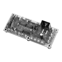
1. Check the 24-volts AC supply voltage
to the circuit card, terminals TB1-1 to
TB1-2. Acceptable range =
21.6 to 26.4 volts AC.
2. Check the 12-volts DC power supply of
the circuit card terminals TB1-5 (+) to
TB1-3 (-). Acceptable range = 11.6 to
12.4 volts DC.
3. Install the magnehelic gage to
observe delta P. When connecting to
the test tees, be careful not to create
an excessively low pressure on the
transducer (when used). The following
procedure should be followed:
a. Remove low-pressure cap from
test tee.
b. Remove high-pressure cap
from test tee.
c. Connect gage to high-
pressure side.
d. Connect gage to low-
pressure side.
Adjustments (Set Maximum and
Minimum Flows)
To set minimum and maximum flows to
the desired setting, refer to the
calibration section.