VAV-SVX03A-EN 7
General
Electronic control systems offer
pressure-independent operation for use
on all single-duct and fan-powered VAV
units (see Figure 3).
The electric air damper used with this
control system has a stroke time (from
open to close) of 90 seconds.
The pressure-independent system will
control room temperature by adjusting
airflow into the space as a function of
zone temperature.
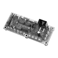
Figure 3 –Electronic Interface Circuit
Boards
Electrical Data
INPUT:
24 VAC, 50 VA maximum
OUTPUT:
1
st
Stage – 24 VAC, 10 VA magnetic
contactors/12 VA mercury contactors
2
nd
Stage – 24 VAC, 10 VA magnetic
contactors/12 VA mercury contactors
3
rd
Stage – 24 VAC, 10 VA magnetic
contactors/12 VA mercury contactors
Cfm Requirements
Maximum Minimum Minimum Heating
Control Unit Cfm Flow Cfm Flow Cfm Flow Setting
Type Size Setting Setting (VCEF Only)
4 38-225 0,38-225 45-225
5 63-350 0,63-350 70-350
6 73-500 0,73-500 100-500
Analog 8 134-900 0,134-900 180-900
Electronic 10 215-1400 0,215-1400 280-1400
12 300-2000 0,300-2000 400-2000
14 408-2890 0,408-2890 578-2890
16 536-3790 0,536-3790 758-3790
24x16 1096-8000 0,1096-8000 1600-8000
Notes:
1. Minimum flow and maximum flow settings must have at least a 0.05 Delta P flow sensor signal difference.
2. Flow rings are provided with all unit sizes.
3. A minimum setting of zero is permissible, except for VCEF units.
Analog
Controls
Electronic Controls Installation
Check the wiring on the unit with the wiring diagram and wiring information label.
Insure that all jumpers are to the proper location and that the actual unit wiring
matches the wiring diagram and wiring label information. See Figure 4.
Units with electronic control options must use Trane zone sensors to be compatible
with the unit circuitry. The analog zone sensor electronics are designed
specifically to operate with the Trane electronic controls; other zone
sensors will not work properly with this unit. The Trane analog zone sensor
must be used in conjunction with these electronic controls. Typically, field
controls wiring include the following:
1. 24 VAC-powered connection to terminals TB1-1 and TB1-2. These are stab terminals
marked one and two on the five-pole terminal strip located in the corner of the
circuit card.
2. Zone sensor connections are to TB1-3,4,5.
3. Heater contact wiring is normally installed in the factory. Should field installation be
required, each wiring diagram shows the field alternate wiring requirements.
Hazardous Voltage!
Disconnect all electric power, including remote disconnects before servicing. Follow
proper lockout/tagout procedures to ensure the power cannot be inadvertently
energized. Failure to disconnect power before servicing could result in death or
serious injury.
WARNINGWARNING