14 VAV-SVX03A-EN
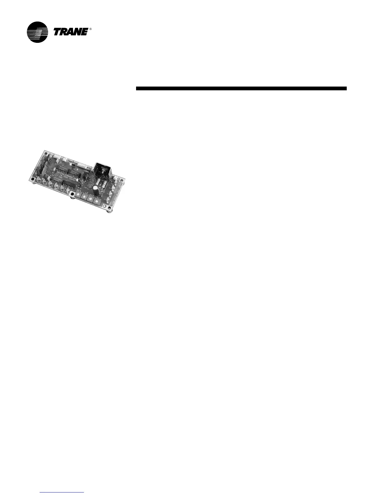
The general layout of the analog circuit
board is shown in Figure 5. The layout of
the circuit card shows the physical
location of each item. Basic connections
are as follows (see Figure 4, page 7):
Figure 5 – Analog Electronic Controller
Installation
and Wiring
1. Power is connected to TB1-1 and TB1-
2. The power requirement is 24 volts
AC (+ 10%).
2. The zone sensor is connected to
terminals TB1-3, 4, and 5. It is very
important not to connect power to
these terminals, since applying power
to the wrong terminal will destroy the
card.
3. The motor is connected via jack J1.
4. The transducer (pressure-
independent) is connected at jack J3.
5. Reheat stages (or fan on fan-powered
units) are connected at jacks J7 (24
VAC), J9, J10, and J11.
6. Various options to cause changes to
the operation of unit are input at
jack J15.
7. There are various adjustments on the
circuit card as discussed in detail in the
Calibration section.
a. Maximum flow (or position)
adjustment is R67. Turning
clockwise increases the
maximum flow.
b. There are two minimum flow
adjustments labeled R68 and
R69. Turning clockwise
increases the minimum flow.
c. There is a zero-flow adjustment
used in initial calibration and set-
up of the circuit card. This is R8.
8. There are four test points for the
convenience of servicing in the field.
These test points include:
TP4: Transducer output
TP1: Flow voltage (null calibration)
TP2: Temperature voltage
TP3: A common to make application of
clip leads easy.