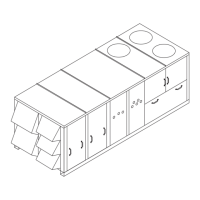
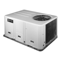
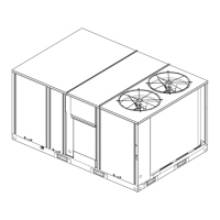
Unit Dimensions and Weights
RT-SVX34F-EN 17
Notes:
• On horizontal units, the VFD is located between the
supply and return ductwork, which makes access
limited.
• For combination of horizontal and downflow openings
(digit 3 = F or R) see Figure 7, p. 16 for appropriate
downflow/upflow dimensions and Figure 8, p. 17 for
appropriate horizontal dimensions.
Note: Dimensions in ( ) are mm, 1”= 25.4 mm.
Figure 8. Duct openings, 60 Hz 40-50, 50 Hz 33-42 Tons (TH, TH, YH low and high heat)
Figure 9. 60 Hz 40-50, 50 Hz 33-42 Tons (TC, TE, YC low and high heat)
7 9/16"
232 3/8"
5902.3mm
232 3/4"
5911.8mm
90 5/8"
49 9/16"
1258.8mm
93 3/8"
2371.7mm
5 5/16"
90 1/16"
77"
1955.8mm
46 15/16"
1192.2mm
4 3/4"
120.6mm
NOTES:
1. SEE ROOFCURB DRAWING FOR DETAILS
ON FIELD DUCT FITUP AND CONNECTIONS
2. SEE DETAIL HOOD DRAWING FOR HORIZONTAL /
DOWNFLOW UNITS FOR ADDITIONAL DIMENSION
AND LOCATION.
SEE NOTE 2
CUSTOMER
CONNECTION POINT
2301.8mm
PVC PIPE FEMALE
1" [25.4MM] NPT
HIGH HEAT GAS INLET
2287.5mm
136.5m
192.1m
3.25 [82.55mm] TO
TOP OF FAN GRILLE
1 1/4" [31.7mm]
3/4" [19MM] NPT
LOW HEAT GAS INLET

 Loading...


