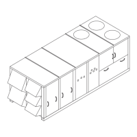
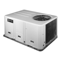
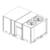
Unit Dimensions and Weights
20 RT-SVX34F-EN
Table 4. Approximate units operating weights — lbs./
kg
1
Unit
Model
Basic Unit Weights
1
YC
Low Heat
YC
High Heat TC TE
**D330/275 3750 1701 4130 1873 3620 1642 3640 1651
**H330/275 3790 1719 4220 1914 3660 1660 3680 1669
**D360/305 3845 1744 4225 1916 3715 1685 3735 1694
**H360/305 3885 1762 4315 1957 3755 1703 3775 1712
**D420/350 3970 1801 4350 1973 3840 1742 3860 1751
**H420/350 4010 1819 4440 2014 3880 1760 3900 1769
**D480/400 4764 2161 4884 2215 4539 2059 4564 2070
**H480/400 4859 2204 4984 2261 4599 2091 4634 2102
**D600/500 5174 2347 5294 2401 4949 2245 4974 2256
**D600/500 5269 2390 5394 2447 5019 2277 5044 2288
Notes:
1. Basic unit weight includes minimum horsepower supply fan
motor.
DE F
TOP VIEW
OF UNIT
COMPRS
CBA
Table 5. Point loading average weight
1,2
— lbs./kg
Model A B C D E F
**D330/275 846 384 688 313 743 337 745 338 604 275 503 228
**H330/275 867 393 707 321 767 348 753 342 613 279 513 233
**D360/305 836 379 680 309 779 353 741 336 621 285 568 258
**H360/305 897 407 696 316 766 348 729 330 590 268 636 288
**D420/350 892 405 692 314 779 353 765 347 633 288 590 268
**H420/350 867 393 869 395 690 313 758 344 601 273 654 297
**D480/400 820 372 856 388 937 425 742 336 762 346 769 349
**H480/400 841 381 876 397 957 434 754 342 775 352 782 355
**D600/500 894 406 955 428 970 440 756 343 862 391 866 393
**H600/500 915 415 966 438 990 449 768 348 875 397 879 399
Notes:
1. Point Loading is identified with corner A being the corner with the
compressors. As you move clockwise around the unit as viewed
from the top, mid-point B, corner C, corner D, mid-point E and
corner F.
2. Point load calculations provided are based on the unit weight for YC
high heat gas models.
Table 6. Approximate operating weights
1
— optional components — lbs./kg
Unit
Model
Baro.
Relief
Power
Exhaust
0-25%
Man
Damper Econ.
Var. Freq.
Drives (VFD’s)
Serv
Valves
Through-
the
base
Elec.
Non-
Fused
Discon.
Switch
Factory.
GFI with
Discon.
Switch
Roof CurbW/O With
Bypass Lo Hi
**D330/275 110/50 165/74 50/23 260/117 85/39 115/52 18/8 6/3 30/14 85/38 310/141 330/150
**H330/300 145/65 200/90 50/23 285/128 85/39 115/52 18/8 6/3 30/14 85/38 310/141 330/150
**D360/305 110/50 165/74 50/23 260/117 85/39 115/52 18/8 6/3 30/14 85/38 310/141 330/150
**H330/305 145/65 200/90 50/23 285/128 85/39 115/52 18/8 6/3 30/14 85/38 310/141 330/150
**D420/350 110/50 165/74 50/23 260/117 85/39 115/52 18/8 6/3 30/14 85/38 310/141 330/150
**H420/350 145/65 200/90 50/23 285/128 85/39 115/52 18/8 6/3 30/14 85/38 310/141 330/150
**D480/400 110/50 165/74 50/23 290/131 115/52 150/68 18/8 6/3 30/14 85/38 365/169 365/169
**H480/400 145/65 200/90 50/23 300/135 115/52 150/68 18/8 6/3 30/14 85/38 365/169 365/169
**D600/500 110/50 165/74 50/23 290/131 115/52 150/68 18/8 6/3 30/14 85/38 365/169 365/169
**H600/500 145/65 200/90 50/23 300/135 115/52 150/68 18/8 6/3 30/14 85/38 365/169 365/169
Note:
1. Basic unit weight includes minimum horsepower supply fan motor.

 Loading...


