Installation
26 RT-SVX21K-EN
Horizontal Discharge Conversion
(3 Through 5 Ton Units)
Note: 3 - 5 ton units supply cover to supply opening and
return cover to return opening.
Supplies needed by installer for conversion: 3 oz. tube of
high temperature RTV sealant. (500°F / 260°C: similar to
Dow Corning 736)
Important: Failure to use recommended sealant could
result in unit performance loss.
If a unit is to be converted to a horizontal discharge, the
following conversion must be performed:
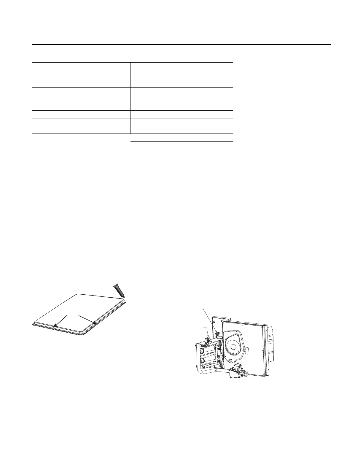
1. Remove RETURN and SUPPLY duct covers.
2. Locate supply cover. Apply ¼ in. (6mm.) continuous
bead of 500°F RTV sealant to the flange as shown.
3. Position duct cover as shown, rotate 90 degrees to
allow entrance into supply opening.
4. Slide duct covers into duct openings until inward edge
of duct cover engages with the 2 retaining clips on the
duct flanges. Secure the outward edge of each duct
cover with 2 screws.
5. Slide RETURN DUCT COVER (insulation side up) into
supply opening until inward edge of duct cover
engages with the 2 retaining clips on the duct flange.
Secure outward edge of the duct cover with two
screws.
6. After completing installation of the duct covers for
horizontal discharge, proceed to TCO-1 instructions.
TCO-1 Instructions
If the unit being installed is listed in the following list, the
limit control TCO1 must be replaced with the extra limit
control shipped in the heater compartment. Replace TCO1
following the instructions in steps 1through 3 below. If the
unit being installed does not correspond to any in the
following list, skip steps1 through 3 and go on to next step
in the installation process.
Unit Model Number
YSC036E**(M,Y), YSC036E**(H,Z), YSC048E**(H,Z),
YSC048E**(M,Y) belt drive ID motor, YSC060E**(H,Z)
direct drive ID motor, YHC047E**(L,X), YHC048E/F**(L,X)
direct drive ID motor, YHC060E/F**(L,X) belt drive ID
motor, YHC036E**(M,Y), YHC037E**(M,Y), YHC048E/
F**(M,Y), YHC060E/F**(M,Y) direct drive ID motor,
YHC036E**(H,Z), YHC048E/F**(H,Z) belt drive ID motor,
YHC060E/F**(H,Z).
Unit Model
(Standard
Efficiency)
TCO1 Tripping
Values
Down flow/
Horizontal
Unit Model
(High Efficiency - 15
SEER)
TCO1 Tripping
Values
Down flow/
Horizontal
YSC102F**(L,X) 225F YHC092F**(M,Y) 180F / 200F
YSC102F**(M,Y) 230F YHC092F**(H,Z) 200F
YSC102F**(H,Z) 200F / 260F YHC102E**(L,X) 135F
YSC120F**(L,X) 180F / 200F YHC102E**(M,Y) 135F
YSC120F**(M,Y) 200F YHC102E**(H,Z) 170F
YSC120F**(H,Z) 190F / 260F YHC120E**(L,X) 135F
YHC120E**(M,Y) 170F
YHC120E**(H,Z) 145F / 190F
Table 3. TC01 tripping values (continued)
Figure 26. Duct cover
Figure 27. TCO1 location (YSC036E-YSC060E, YHC036E,
YHC037E)
FLAMEFLAME
ROLLOUTROLLOUT
LIMIT LIMIT
LOCATION OF TCO1 LIMIT LOCATION OF TCO1 LIMIT
FOR THE Y(S/H)C036E, YHC037E, FOR THE Y(S/H)C036E, YHC037E,
YSC048E, AND YSC060E UNITSYSC048E, AND YSC060E UNITS