Installation
32 RT-SVX21K-EN
Standard Wiring
1. Location of the applicable electrical service entrance is
illustrated in “Unit Dimensions,” p. 12. Complete the
unit’s power wiring connections at Compressor
Contactor # 1 (CC1) inside the unit control panel. Refer
to the customer connection diagram that is shipped
with the unit for specific termination points
2. Provide proper grounding for the unit in accordance
with local and national codes.
Optional TBUE Wiring (Through the Base
Electrical Option)
1. Location of the applicable electrical service is
illustrated below. Refer to the customer connection
diagram that is shipped with the unit for specific
termination points. The termination points, depending
on the customer option selected would be a factory
mounted non-fused disconnect switch (UDC) or circuit
breaker (UCB). If neither a factory mounted non-fused
disconnect switch (UDC) or circuit breaker (UCB) was
factory mounted, field wiring connections should be
terminated in the control box at Compressor Contactor
# 1 (CC1).
2. Provide proper grounding for the unit in accordance
with local and national codes.
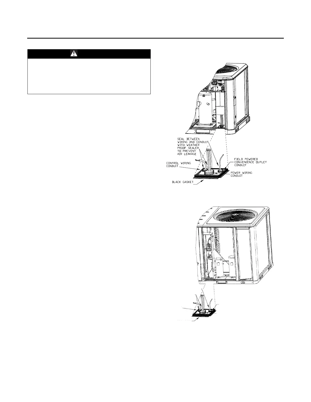
Note: Black Gasket is shipped from the factory and is
located in the literature Ship With bag in the control
box. Apply Black Gasket around conduit plate on all
4 sides after installation to prevent air leakage from
the building entering the electrical enclosures.
Note: Seal between wiring and conduit with Black Gasket
or weather proof sealer to prevent air leakage from
the building entering the electrical enclosures. Also
seal around conduit and wiring at all roof and curb
penetrations.
Field Installed Control Wiring
An overall layout of the various control options available
with the required number of conductors for each control
device is illustrated in Figure 36, p. 30.
Note: All field wiring must conform to NEC guidelines as
well as state and local codes.
WARNING
Hazardous Voltage!
Disconnect all electric power, including remote
disconnects before servicing. Follow proper lockout/
tagout procedures to ensure the power can not be
inadvertently energized. Failure to disconnect power
before servicing could result in death or serious injury.
Figure 38. All units except 7½ (dehumidification)-10 ton
high efficiency units
Figure 39. 7½ (dehumidification)-10 ton high efficiency
units
CONTROL WIRING
CONDUIT
BLACK GASKET
CONTROL WIRING
CONDUIT
FIELD POWERED
CONVENIENCE OUTLET
CONDUIT
SEAL BETWEEN
WIRING AND
CONDUIT WITH
WEATHER PROOF
SEALER TO PREVENT
AIR LEAKAGE