iii
LIST OF FIGURES
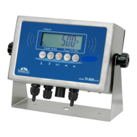
1-1 TI-500-EU Front Panel............................................................................................................ 1-1
2-1 TI-500-EU Main Circuit Board Overview................................................................................. 2-1
2-2 Connection Assignments for the Load Cell Terminal (J1) ...................................................... 2-1
2-3 Connection Assignments for the serial communication Terminal........................................... 2-2
3-1 Setup Menu Key Assignments................................................................................................ 3-1
3-2 Setup Menu Chart................................................................................................................... 3-2
3-3 User Menu Key Assignments.................................................................................................. 3-3
3-4 User Menu Chart..................................................................................................................... 3-3
5-1 User Menu Key Assignments.................................................................................................. 5-2
6-1 Setup Menu Key Assignments................................................................................................ 6-1
7-1 TI-500-EU LCD Detail............................................................................................................. 7-1
7-2 Function Keys Layout ............................................................................................................. 7-2
B-1 Cable Diagram for Indicator to IBM PC .................................................................................. B-1
B-2 Consolidated Controls Demand Mode.................................................................................... B-1
B-3 Print Ticket .............................................................................................................................. B-2
B-4 Cable Diagram for Indicator to Printer .................................................................................... B-2
B-5 Consolidated Controls Continuous Mode ............................................................................... B-3
LIST OF TABLES
6-1 Calibration Value Table........................................................................................................... 6-2
7-1 TI-500-EU Annunciator Definitions ......................................................................................... 7-1
C-1 Minimum Recommended Span Gain Table............................................................................ C-2