CHAPTER 2: INSTALLATION
2.1 STAINLESS STEEL ENCLOSURE
For indicators contained in a stainless steel enclosure, the rear cover must first be removed to
make the appropriate connections to the weigh platform, printer, remote display and power supply.
o remove the rear cover, simply remove the screws that secure it to the enclosure and set aside.
T
NOTE: The rear cover must remain off to access the Setup Menu and calibration procedures.
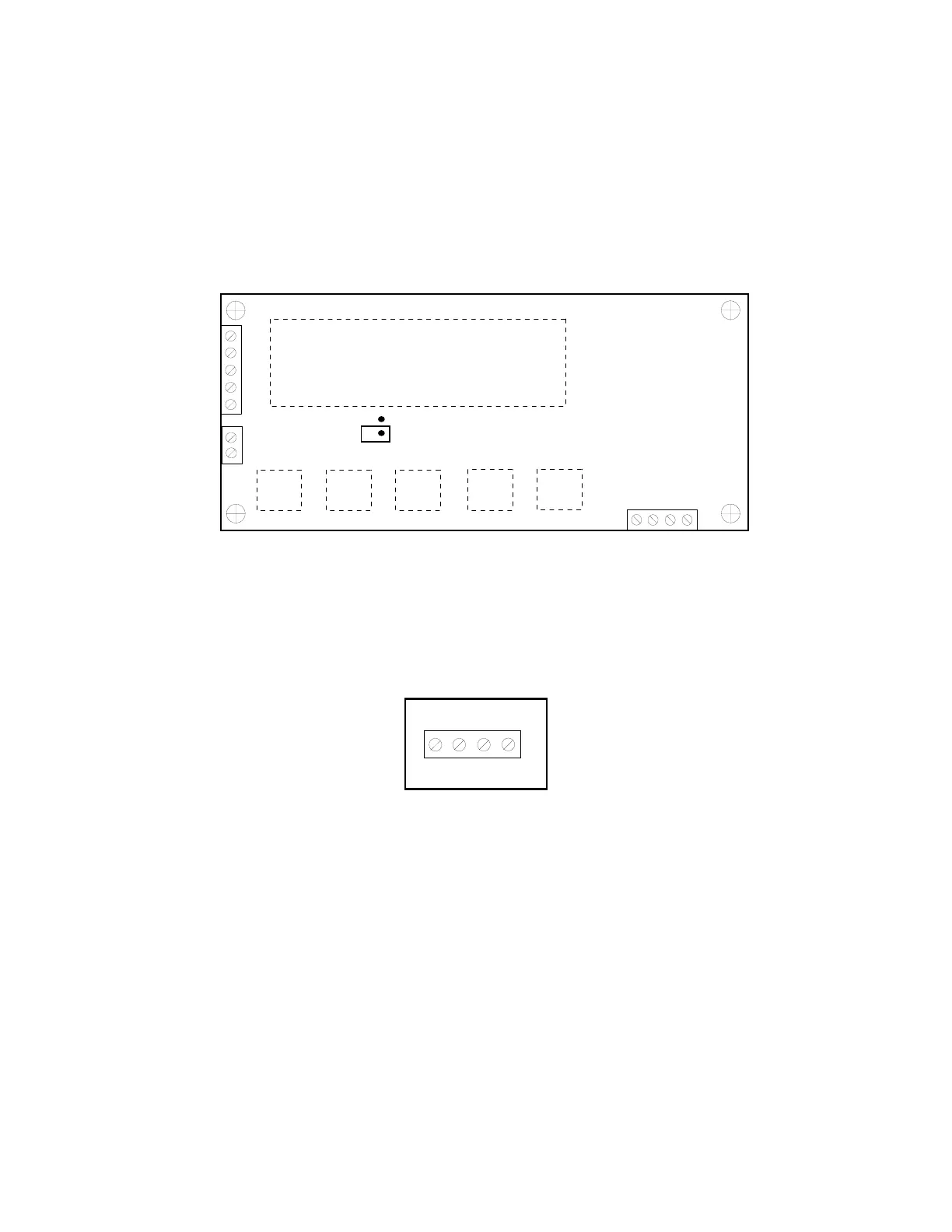
J1
S+E+
S-
E-
P-
J2
P+
JP4
J3
TXD
RXD
GND
P-
nc
nc
Figure 2-1: TI-500-EU Main Circuit Board Overview
2.1.1 CONNECTING THE WEIGH PLATFORM
1. Connect your shielded load cell cable (not included) to terminal J1 on the main board.
Connection assignments for the Load Cell Terminal (J1) are shown in Figure 2-2.
J1
E+
S–
E-S+
Figure 2-2: Connection assignments for the Load Cell Terminal (J1)
2.1.2 CONNECTING THE SERIAL PRINTER, REMOTE DISPLAY OR COMPUTER
The TI-500-EU indicator comes standard with one full duplex RS-232 serial port, designed
for connection to either a PC or a serial printer. The same port may be also used as a
simplex, RS-232 port designed for connection to a remote display.
For indicators housed in a Stainless Steel enclosure, this port is realized in J3. Connection
assignments for all serial communication terminals are shown in Figure 2-3.
1. Connect your serial printer, remote display or computer communication cable (not
included) to terminal J3 on the main board.
Page 2-1