Encompass 4 Reader
TransCore Proprietary
15
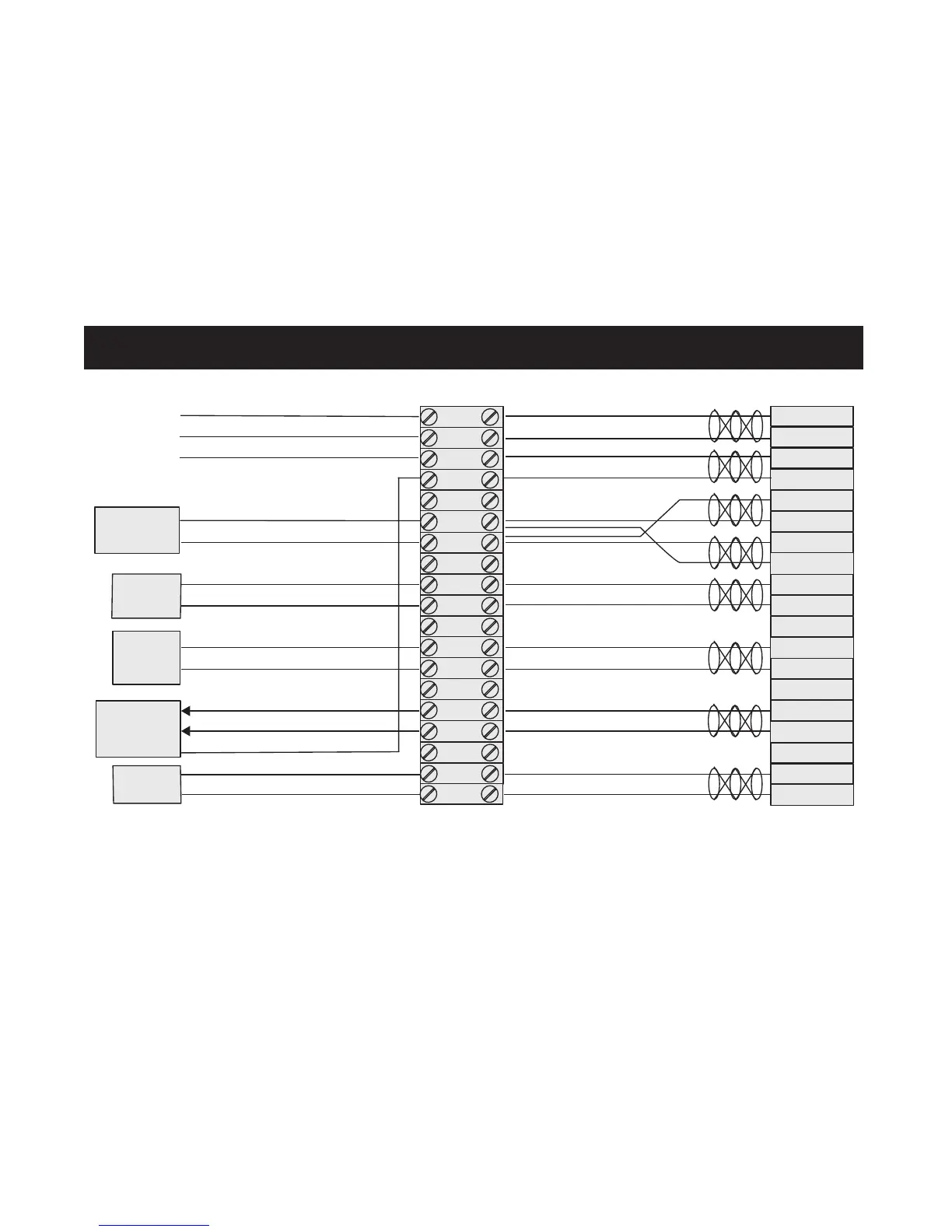
Figure 3 RS–232 Wiring Diagram
Gate Controller
with Wiegand
Input
Blue (Blue/Red Pair), DATA0 for Wiegand
Twisted Pairs
Red
Orange
Red
Brown
Black (Black/Brown Pair), Form C (C)
Red/Red
2
Wiring Diagram for an Encompass® 4 (RS–232) Unit
Terminal Block Encompass 4 Connector
RS–232
RxD, Pin2 for DB9 or Pin3 for DB25
TxD, Pin3 for DB9 or Pin2 for DB25
SIG GND, Pin5 for DB9 or Pin7 for DB25
Red (Black/Red) to Reader Rápido Transformer
Black (Black/Red) to Reader Rápido Transformer
Low Current, Pulsed Relay (C) Closure Output
Low Current, Pulsed Relay (NO) Closure Output
To Plus (+) side of 6-12V DC Buzzer
To Plus (+) side of 9V Battery
Connection to Wiegand device (DATA1)
Connection to Wiegand device (DATA0)
Connection to Wiegand device (SIG GND)
1
3
4
5 (NC)
6
7
8 (NC)
9
10
11 (NC)
12
13
14 (NC)
15
16
A
B
b
H
G
K
J
T
U
L
M
E
F
N
P
Red (Black/Red Pair) RxD
Black (Black/Red Pair) TxD
Yellow (Yellow/Black Pair) Signal Ground
Black (Yellow/Black Pair) Signal Ground
Orange/Brown
Black (Black/Brown Pair), Form C (NO)
White (White/Red Pair), Tag Lock Output
Red (White/Red Pair), Tag Lock Output Return
Red (Blue/Red Pair), DATA1 for Wiegand
Green (Green/Red Pair), Presence detect
Red (Green/Red Pair), Presence detect
L1
L2
18V AC
Transformer
Dry Contact
ext. gate relay
Audible
alarm (Buzzer
w/ Battery)
WD-0113
Loop Detector
c
b
17
18
19


 To Next Page