REAR PANEL CONNECTOR
The rear panel includes a green, five-way
binding post. This is a return connection for
the low side of the load and/or a ground ref-
erence point for other equipment.
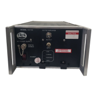
OPERATING PROCEDURE
The 50/750 may be used as either a high-
voltage amplifier or as a high voltage refer-
ence supply. The operation is the same for
both applications: an external, low voltage
signal is applied to the input connector and
a proportional high-voltage signal is deliv-
ered through the output connector to the
load device.
WARNING: The high-voltage OUTPUT con-
nector carries high voltage. DO NOT touch
the high voltage OUTPUT connector or the
load circuit while the 50/750 is operating.
An electrical shock could result. Always
turn off the amplifier before making changes
to the load connection.
1. Ensure that the POWER switch is off
before connecting the input signal and
the load.
2. Connect the input signal to the INPUT
receptacle. Ensure that the amplitude of
the input signal does not exceed the
input voltage range specified for the
selected channel and that the source
current is limited to 100 mA.
3. Connect the output signal to the load
circuit using the high-voltage connector/
cable assembly previously constructed.
4. Turn on the POWER switch.
ADJUSTING THE GAIN
NOTE: Unless a different gain was speci-
fied at the time of order, the gain was set at
150 V/V when the 50/750 was shipped from
the factory.
To set the Gain for a different value:
1. Ensure that the 50/750 POWER switch
is off before connecting the input signal
and the digital voltmeter.
2. Connect the output of a DC reference
supply to the INPUT of the 50/750.
3. Connect the output signal to a digital
volt-meter. Ensure that the digital
voltmeter has an input voltage rating
higher than ±1500 V.
4. Turn on the POWER switch.
5. Adjust the gain potentiometer until the
desired gain is obtained. The gain pot is
accessed through the GAIN hole in the
front panel. Use a small screwdriver,
preferably nonconductive.
ADJUSTING THE AC RESPONSE
CONTROLS
As shipped from the factory, the AC
response controls, RESPONSE and DAMP-
ING, are optimized for a no-load condition.
You may desire to readjust these controls
for your load.
NOTE: If it is not feasible to apply the test
signal stated below to your particular load
device, substitute an equivalent RLC load
for the purpose of setting the AC response
controls.
Optimizing the AC Response with a Load
Connected
1. Apply a 100 Hz square wave to the input
of the 50/750. The amplitude of the
square wave must cause a full scale
output excursion: ±5 V in for -750 V to
+750 V out, 0 to +10 V in for 0 to +1500
V out, and 0 to -10 V in for 0 to -1500 V
out (values for a gain of 150).