SECTION III
OPERATION
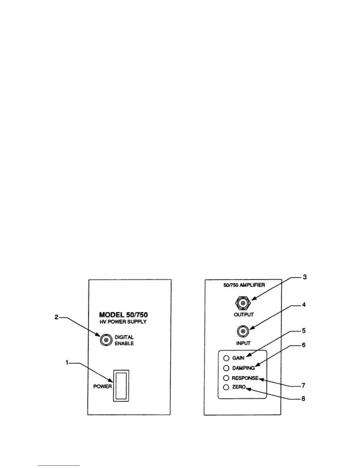
FRONT PANEL CONTROLS and INDICATORS
Refer to figure below for the location of the
controls and indicators.
1. POWER Switch: This switch turns the
50/750 on and off. A red lamp in this switch
assembly glows when the 50/750 is on.
2. DIGITAL ENABLE: Connect a switch,
relay, or TTL control signal to this input to
turn the high voltage on and off.
3. H.V. OUTPUT: This receptacle, using the
MHV connector (provided), is for the
connection to the load device.
4. AMPLIFIER INPUT: This BNC input
connector is for the connection to an
external, low voltage signal source.
5. GAIN Control: The gain control allows the
user to adjust the DC gain from 15 to 300
V/V. The gain is factory set at 150 V/V
unless otherwise specified when ordered.
6. DAMPING Control: Use this control in
conjunction with the RESPONSE control to
optimize the step response characteristics
of the amplifier.
7. RESPONSE Control: Use this control in
conjunction with the DAMPING control to
optimize the step response characteristics
of the amplifier.
8. ZERO Control: Use this control to produce
zero voltage at the OUTPUT when the input
signal is zero.
7