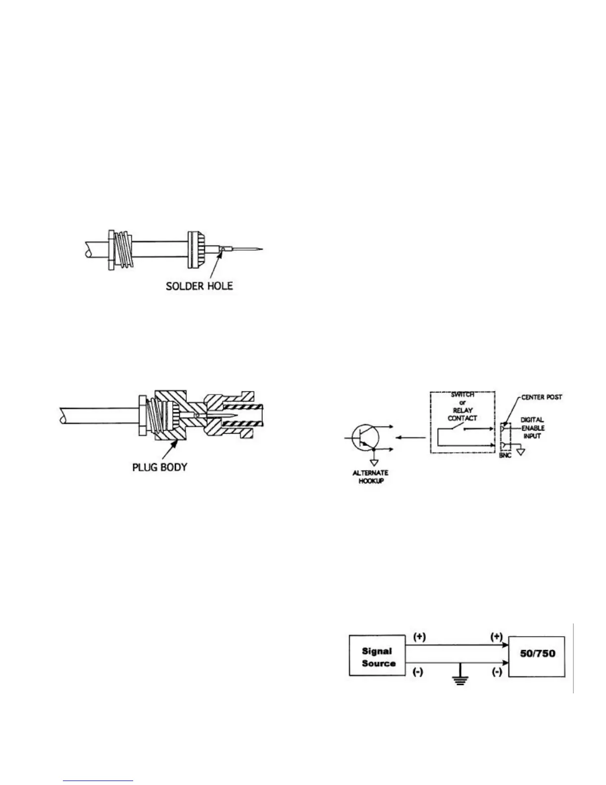
4. Solder the contact onto the conductor
through the solder hole. The contact
should butt flush against the dielectric.
Remove excess solder from outside of
the contact.
CAUTION: Avoid applying excess heat
to the contact. This will cause the
dielectric to swell and interfere with the
connector body.
5. Push the contact assembly into the con-
nector body. Screw the nut into the
body with a wrench until tight. Do not
rotate the connector body on the cable
assembly to tighten.
This completes the high voltage connector/
cable assembly procedure.
LOAD CONNECTIONS
Load connections should be made as short
and direct as possible.
1. Connect the center conductor of the
high-voltage cable to the “hot” side of
the load.
2. Return the low side of the load to the
shield of the coaxial cable or to the
green, five-way binding post on the rear
panel of the amplifier.
DIGITAL ENABLE CONNECTION
The DIGITAL ENABLE connection is made
at the DIGITAL ENABLE BNC connector on
the front panel of the POWER SUPPLY
module. To control the 50/750 from a
remote device, connect this input to ground
through a switch or relay contact, or connect
it to the output of a controlling device such
as an open collector transistor or TTL gate
that has a current sinking capability of
approximately 2 mA. When contact is made
from the center post to ground (or the BNC
connector shield), both channels are
enabled. When contact is broken, the high-
voltage rails to both channels are disabled.
When a remote enable/disable function is
not required, connect the cap over the
DIGITAL ENABLE receptacle. This shorts
the DIGITAL ENABLE input and allows the
50/750 to operate.
INPUT CONNECTIONS
To prevent noise pickup, the ground refer-
ence for the input signal must be connected
to the input BNC connector shield. See
diagram below.