4 RS-WMB, RD-WMB Installation Instructions TG201349 Issue 4, 26-Aug-2015. Applies to 1.02.2.
RS-WMB, RD-WMB Installation Instructions
8
Congure Controller Strategy (not pre-congured controllers)
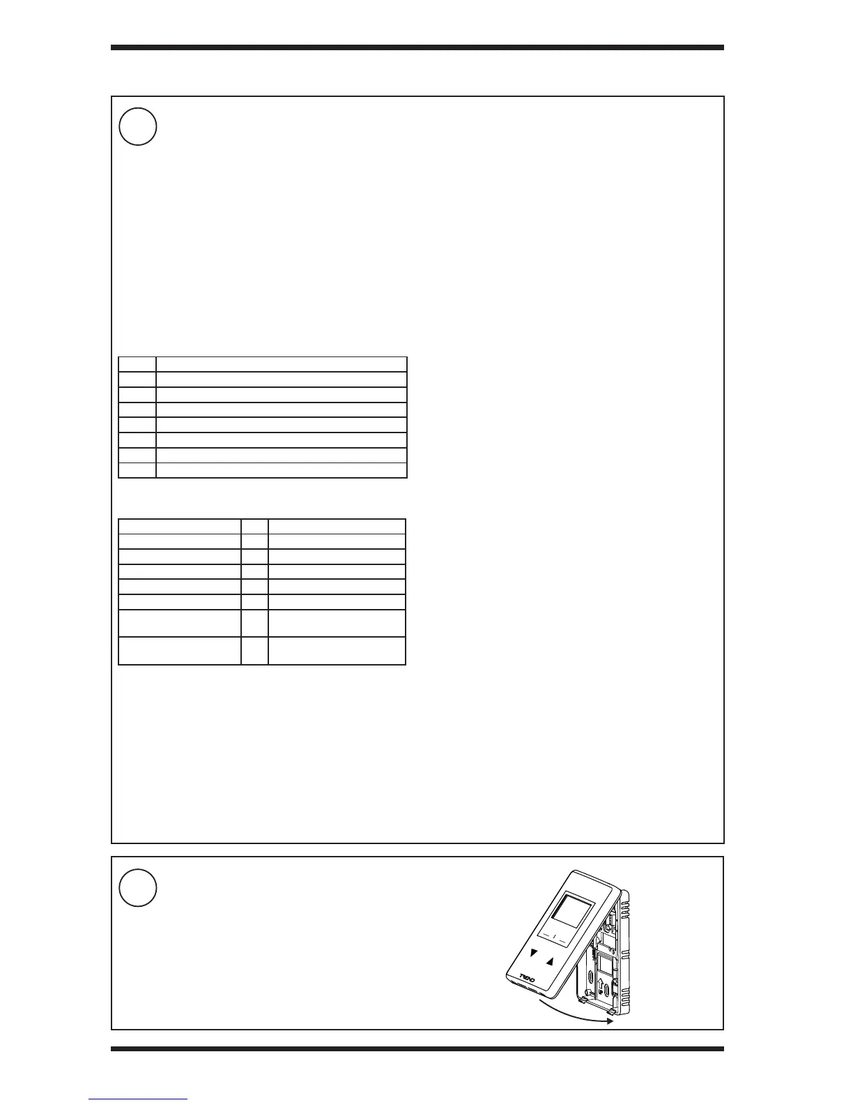
9
Replace Front Panel
3 INSTALLATION (continued)
Use with IQ4
The IQ4 can be congured either by using the SET strategy
block (recommended), or by manual conguration.
Using the SET strategy block (recommended):
▪ Add the SET Strategy Block to the strategy. The
strategy blocks are located in the ‘Standard Block’
section of the Strategy Library in the ‘WMB Room
Modules’ section. There is a separate section for RS
and RD, each section has 4 blocks, one block for each
product version (-T, -TC, -TH, -THC).
▪ Set the Wallbus Interface module’s ‘Address’
parameter to the RS-WMB, RD-WMB’s address on
the Wallbus (default is 2.)
▪ Ensure that the Wallbus Interface module’s inputs and
outputs are linked to the required modules.
Important: When using the strategy block (as explained
above) some PVs write their value to the RD-WMB and will
overwrite changes to that PV made in the RD-WMB’s Settings
Menu. If this is not required, remove the PV from the Wallbus
Interface module’s inputs. See RS-WMB, RD-WMB Data
Sheet (TA201348).
Adding the strategy block will automatically add the Wallbus
Network module, and create an instance of the Wallbus
Interface module.
The strategy block congures the inputs and outputs of the
Wallbus Interface module - see RS-WMB, RD-WMB Data
Sheet (TA201348). This conguration should be suitable for
most applications. If different functionality is required the
strategy will need to be modied after the strategy block has
been added.
Manual conguration:
▪ Add the Wallbus Network module to the strategy
(default values will be suitable).
▪ Add a Wallbus Interface module to the strategy.
▪ SET the Wallbus Interface module’s ‘Address’
parameter to the RS-WMB, RD-WMB’s address on
the Wallbus.
▪ Set up the Wallbus Interface module’s input and
output connections to specify the PV (PV Index) in the
RS-WMB, RD-WMB that they are to be linked to as well
as their other parameters. The RS-WMB, RD-WMB’s
PVs are described in the RS-WMB, RD-WMB Data
Sheet (TA201348).
▪ Link the Wallbus Interface module’s inputs and outputs
to the required modules in the strategy.
For details of the Wallbus Network and Wallbus Interface
modules see the IQ4 Conguration Manual (TE201263).
The controller strategy must be congured using SET v7.0 or greater. For details of using SET - see the SET Manual
(TE200147).
For IQeco
I/Omodule 2 must be set up with WMB display type. Its
channels are connected to external sensors with scaling type
‘112, WMB pre-scaled’ as follows:
Channel 1: Temperature
Channel 2: Humidity*
Channel 3: Dew point*
*Humidity and Dew point on -H, CO
2
on -C versions only
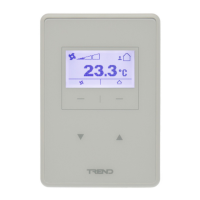
The fan can operate in one of seven modes, this is set in I/O
module 2, Fan Conguration parameter (f). It is set up in the
RD by the controller on power up.
Mode Description
0 no fan
1 2 position fan (OFF, ON)
2 3 position fan (OFF, ON, AUTO)
3 4 position fan (Off, 1, 2, 3)
4 5 position fan (Off, 1, 2, 3, AUTO)
5 4 position blind
6 5 position blind.
The strategy must comply with the following module mappings
between strategy and RS-WMB, RD-WMB .
Setpoint K44 Input to/output from RD
 Loading...