T4
-6-
T4
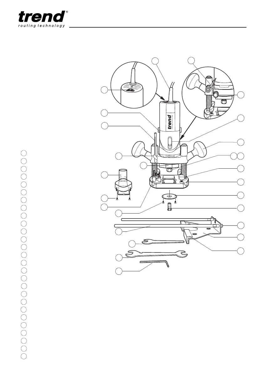
DESCRIPTION OF PARTS
A Plunge locking lever
B Depth stop
C Motor to base locking nut
D Motor housing
E Power cable
F On/Off switch
G Grip knob
H Variable speed control dial
I Collet nut
J
Collet spring (fitted behind collet)
K
Thumb knob to secure fence rods
L
Router base
M
Template guide bush dia.16mm
N
Collet
O
Removable fence cheek
P
Side-fence rod fixing screw
Q
Hex key for side-fence rods
R
Side-fence body
S
Spanner (14mm A/F) for spindle when in grinder mode
T
3-way turret stop
U
Spanner (17mm A/F) for collet nut
V
Thumb knob for depth stop
W
Fence guide rods dia. 8mm x 300mm long
X
Dust spout fixing screw
Y
Template guide bush fixing screw
Z
Dust spout 34mm dia.
AA
Spindle lock
.
.
.
.
.
.
.
.
.
.
.
.
.
.
.
.
.
.
.
.
.
K
L
IJ
G
F
C
M
N
P
O
Q
S
U
W
Y
T
Z
.
AA
.
X
V
B
D
H
E
A
.
R
.
.
MANU/T4 v2.0 30/8/07 1:08 pm Page 6