14
OIL SUPPLY (cont.)
Single-Pipe Oil Supply (Fig. 12)
Where the lowermost part of the tank is above the level of
the burner, a single-pipe gravity system can be used. The oil
supply pipe should be connected to the suction port on the
burner pump via the flexible hose supplied.
Two-Pipe Oil Supply (Fig. 13)
Where the lowermost part of the tank is below the level of
the burner, a two-pipe suction lift is necessary.
When using the two-pipe system, it is important to convert
the suction pump on the burner to operate as such: remove
the end cover and filter, then remove the bottom screw and
the ‘U’ washer. Replace the screw, making sure it is fully
inserted. See the burner details leaflet for further information.
A spring-loaded non-return valve must be fitted in the suction
line to prevent the oil running back to the tank. No valves are
permitted in the return line.
An additional flexible oil line is also required.
Notes:
1. The pump suction should not exceed 0.4bar, as dissolved
gas may be released from the oil, affecting combustion.
2. The return pipe must end at the same level as the suction
outlet to prevent loss of prime.
3. The outlet from the tank should be approximately 75mm (3”)
above the bottom to prevent sediment and water being
drawn into the supply line.
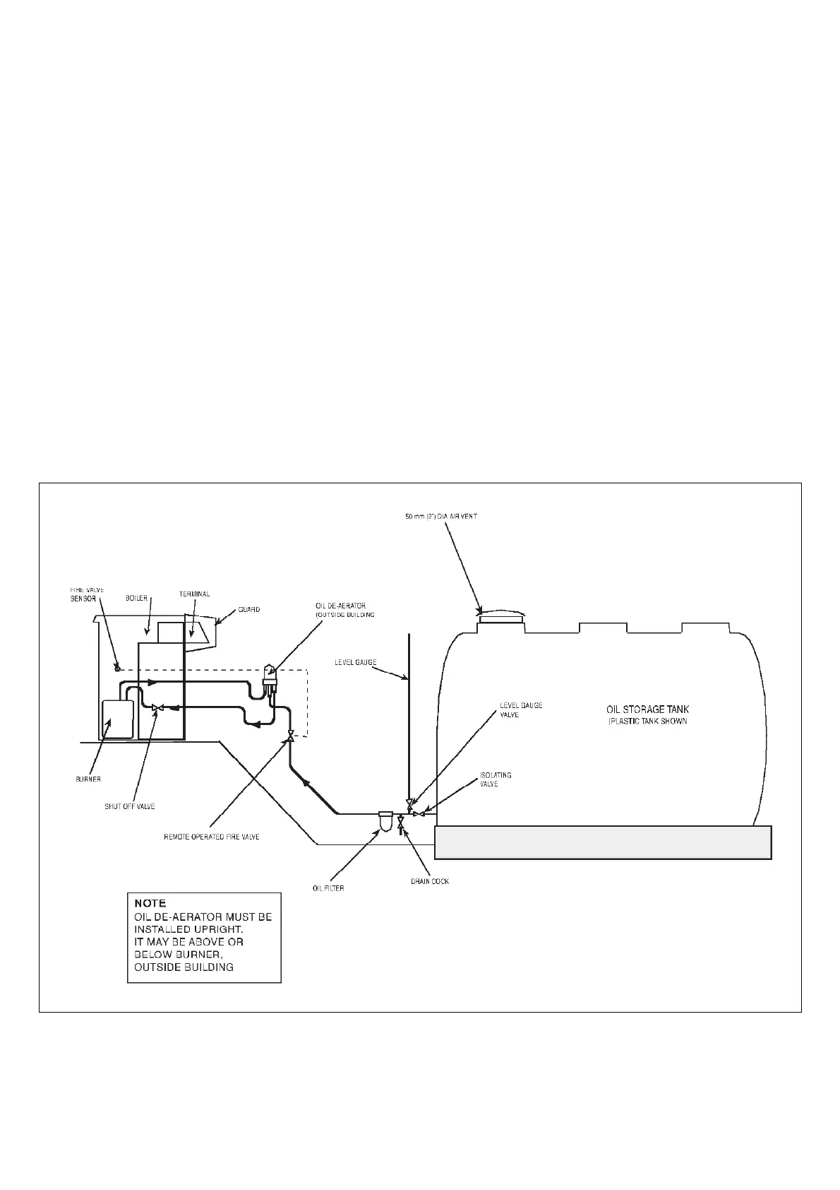
Single-Pipe Oil Supply with De-aerator (Fig. 11)
Where a two-pipe suction lift is required, but the return pipe
requirement is too long, or impractical to run, an oil de-aerator
can be used. The burner should be piped as for a two-pipe
system, up until the de-aerator, when a single pipe can be taken
the remaining distance to the storage tank. The de-aerator
should be fitted at the closest point to the boiler, externally to the
premises.
A non-return valve is not required with this system, but the ‘U’
washer must be removed in the same manner as a standard two-
pipe system.
FIG. 11
INSTRUCTIONS FOR OIL DE-AERATOR
INSTALLATION DETAILS