PRESTIGE Solo 60, 110, 175 and 250
HX Field Replacement
Kit
4
3. In case of insufficient space above the boiler,
remove combustion air inlet piping and boiler
relief valve / air vent assembly from the top of
the boiler. Remove all screws securing the top
jacket panel from the side panels and remove
vent outlet adapter and top jacket panel togeth-
er from the boiler cabinet. Put all items in a safe
place as they will all be reused.
4. Once the vent outlet adapter is removed from the
boiler, it should be inspected for deformation
damage or corrosion.
If there are any signs of deformation, damage or
corrosion on the vent outlet adapter, replace it
immediately. Check condition of flue sensor
mounting, replace vent outlet adapter if necessary.
Failure to comply could result in flue gas leakage
resulting in severe personal injury or death.
Polypropylene Vent Outlet Adapter Removal
1. Dismount the vent outlet adapter from top of boil-
er cabinet by twisting the vent outlet adapter
counter clockwise to disengage the retaining tabs.
Remove the vent outlet adapter by lifting verti-
cally to disengage it from the internal vent pipe.
2. Remove the internal vent pipe from the unit by
lifting vertically upward and out of the boiler
cabinet using a twisting / rocking motion.
Removal of Electrical Connections (MCBA)
Before disconnecting any wire connections mark and
label all connections and location of the connections.
1. Remove top access panel located above the heat
exchanger on the top jacket panel.
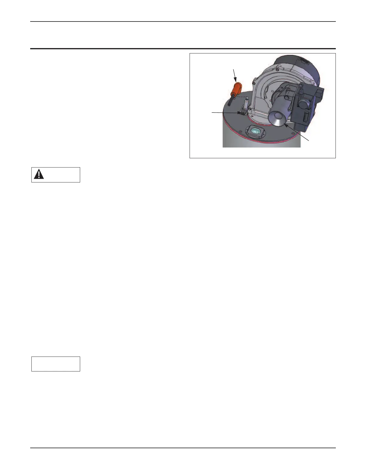
2. Remove ignition cable and green ground wire
from the igniter. (Fig. 6).
3. Disconnect the ignition cable from the MCBA
control module and remove air intake pipe from
venturi. (Shown as item 2 in Figs 1-3). Place
the intake pipe and ignition cable aside, DO
NOT discard as they will be re-used.
4. Disconnect the electrical connection(s) for the
blower at the blower housing.
5. Remove the mounting screw and disconnect the
black rectifier plug from the gas valve.
6. Disconnect the grey flat ribbon cable from the
display board at the MCBA control module.
7. Disconnect the orange low voltage and high volt-
age wiring terminal strips by unplugging the bot-
tom strips from the upper portion.
8. Remove the retaining screw for control mount-
ing panel and swing open the control mounting
panel. The high voltage and low voltage termi-
nals should pass through the lower cutouts of
the panel to allow movement of the panel.
9. Disconnect the red wire leads from supply tem-
perature sensor (Shown as item 3 in Figs 1-3)
located at the top of the heat exchanger.
10. Disconnect the blue wire leads from return tem-
perature sensor (Shown as item 4 in Figs 1-3)
located at the bottom of the heat exchanger.
NOTICE
WARNING
Ignition
Cable
Igniter
Venturi
Fig. 6: Top of Heat Exchanger
 Loading...


