5
CRYSTAL
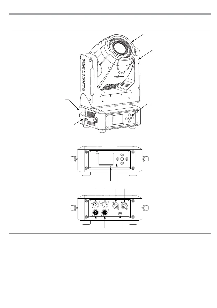
1.3 OPERATING ELEMENTS AND CONNECTIONS
View A
View B
1. MOVING HEAD
2. ROTARY ARM
3. HANDLE
4. LED INDICATOR "WDMX"
5. MICROPHONE
6. CONTROL PANEL with LCD display and 5
button used to access the control panel
functions and manage them.
7. DMX OUT ( 3-pole XLR):
1 = ground, 2 = DMX -, 3 = DMX +
8. DMX IN (3-pole XLR):
1 = ground, 2 = DMX -, 3 = DMX +
9. DMX OUT (5-pole XLR):
1 = ground, 2 = DMX-, 3 = DMX+, 4 N/C, 5 N/C
10. DMX IN (5-pole XLR):
1 = ground, 2 = DMX-, 3 = DMX+, 4 N/C, 5 N/C
11. POWER IN (PowerCON IN): for connection to a
socket (100-240V~/50-60Hz) via the supplied
mains cable.
12. POWER OUT (PowerCON OUT): power output
for connection of multiple units in series.
13. MAIN FUSE HOLDER: replace a burnt-out fuse
by one of the same type only (T3.15A/250V).
Fig.2
4
7
8
9
10
A
B
1
2
3
5
6
11 12
13