PDx-170-57-E / TMCM-170 Hardware Manual (V1.10 / 2011-NOV-24) 6
Copyright © 2011, TRINAMIC Motion Control GmbH & Co. KG
4 Electrical and mechanical description
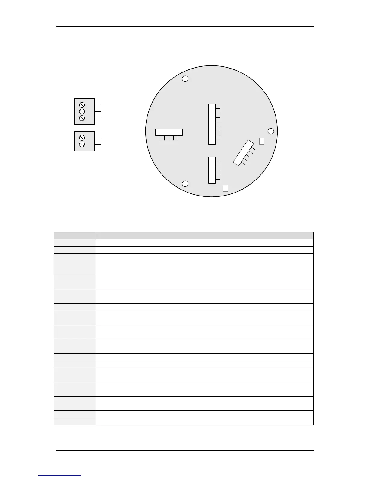
4.1 Pinning
Connectors shown as top view
3
2
1
W
V
U
Motor / power supply
connector on bottom PCB
Hall
sensors
1.5mm
conn.
1
2
3
4
5
+5V
GND
H1
H2
H3
Inter-
face
5
4
3
2
1
RS485- / TXD
RS485+ / RXD
GND
CANL
CANH
Encoder
5
4
3
2
1
CHB
CHA
CHN/Null
GND
+5V
I/O
8
7
6
5
4
+5V
CUR LED
GND
OVT LED
DIRIN
3
2
1 AIN
N.C.
/STOP
2
1
GND
VS
RS485 Term
CAN Term
Analog input: Can measure 0 - 10V signal.
5V TTL input. Not used in current firmware releases
Reference Switch / Emergency stop. Tie this pin to GND to stop the motor or to clear
the position counter. Function / polarity depends on Software setting.
(5V TTL input with integrated 10K pull-up resistor to 5V)
5V TTL output: Toggling with 3Hz when temperature pre-warning threshold is
exceeded, high when module shut down due to overtemperature.
5V TTL output: High, when module goes into current limiting mode or into
overvoltage switch off. Toggling with 3Hz on undervoltage condition.
5V supply for motor hall sensors and as reference for external purpose
Power GND / GND reference
GND is also connected to the mounting holes on the bottom PCB
RXD signal of module for RS232 communication (RS232 version)
Non-inverting RS485 signal (RS485 version)
TXD signal of module for RS232 communication (RS232 version)
Inverting RS485 signal (RS485 version)
Encoder null channel (optional use)
(5V TTL input with integrated pull-up resistor to 5V)
Incremental encoder channel A / channel B
(5V TTL input with integrated pull-up resistor to 5V)
Hall sensor signals
(5V TTL input with integrated pull-up resistor to 5V)
Positive power supply voltage (reverse polarity protected)
Leave all other pins unconnected!