EasyManuals Logo

Trinamic TMCM-170-57 User Manual

Trinamic TMCM-170-57
18 pages
To Next Page IconTo Next Page
To Previous Page IconTo Previous Page
Page #7 background imageLoading...
Page #7 background image
PDx-170-57-E / TMCM-170 Hardware Manual (V1.10 / 2011-NOV-24) 7
Copyright © 2011, TRINAMIC Motion Control GmbH & Co. KG
I/O board
(top view)
1
2
3
4
5
Interface
1
2
3
4
5
6
7
8
I/O
1
2
3
4
5
Hall
sensors
1
2
3
4
5
Encoder
Driver board
(top view)
Motor
U V W
Power
+
Interface
EncI/O
Hall
Motor Power
Important note: For the PANdrives PD-170, the motor coils, hall sensor signals and encoder signals
are already connected. Nevertheless, in order to connect power supply the upper interface board has
to be removed. Never connect or disconnect the boards while power is switched on!
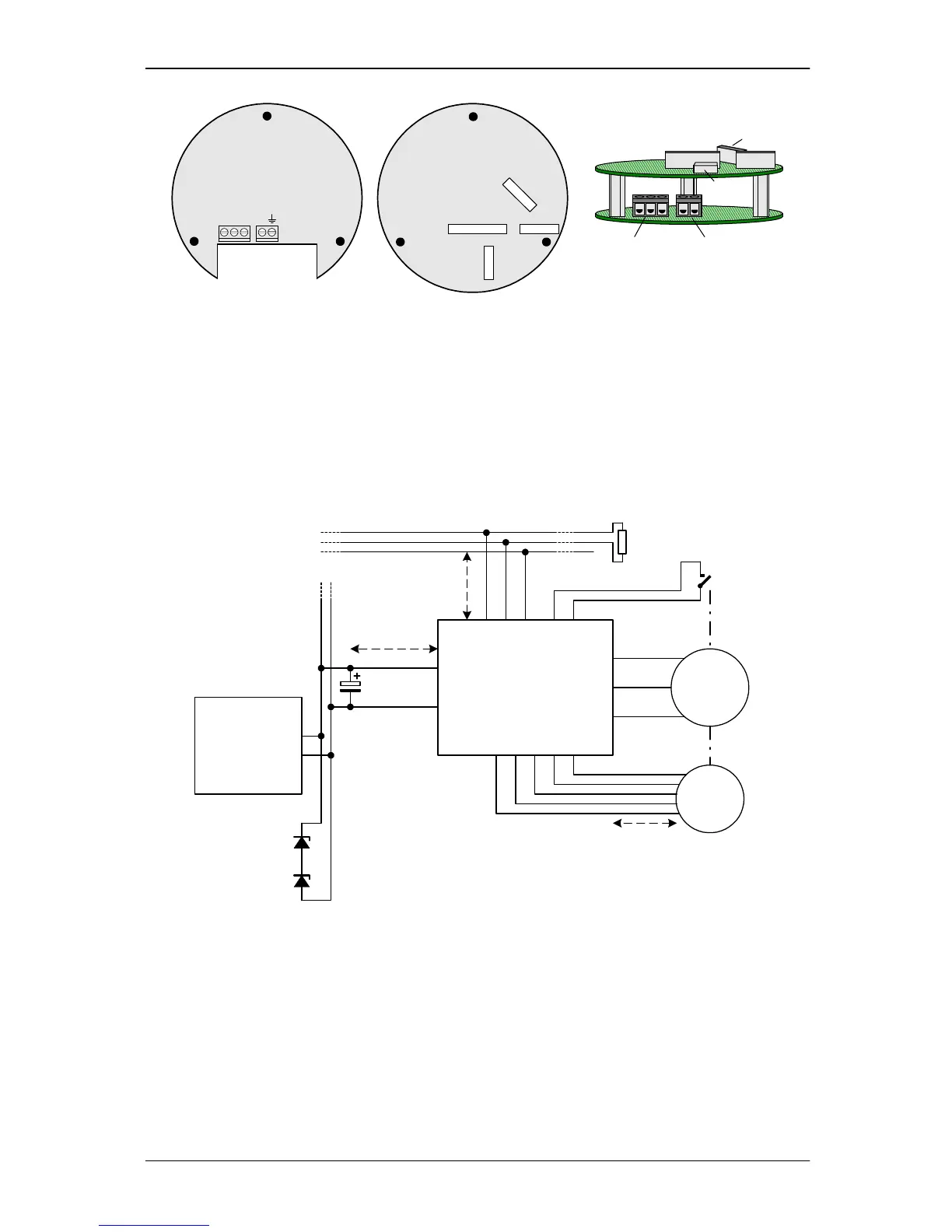
4.2 Application circuit
The schematic shows a typical application circuit using CAN bus interface. Optionally the unit allows
connection of motor hall sensors and encoder N-channel as well as further digital / analog pins and
different interface options.
Figure 4.2: Application circuit

Questions and Answers:

Question and Answer IconNeed help?

Do you have a question about the Trinamic TMCM-170-57 and is the answer not in the manual?

Trinamic TMCM-170-57 Specifications

General IconGeneral
BrandTrinamic
ModelTMCM-170-57
CategoryController
LanguageEnglish