Do you have a question about the Trinity NF29 and is the answer not in the manual?
Connects Trinity NF29 Meter RS485 terminals to TrackSo IoT Gateway, specifying Data+ and Data- pins.
Specifies default Inverter ID, Baud Rate, Data Bits, Stop Bit, and Parity for the TrackSo IoT Gateway.
Details entering programming mode on the meter to set parameters for RS485 communication.
Step-by-step guide to set the meter's address (1-255) using the unit's keys in programming mode.
Instructions for ensuring correct connections, inserting SIM, and powering on the TrackSo device.
Explanation of LED meanings for Power, GSM (SIM, Network, GPRS), COM TX, and COM RX.
Sending an SMS command to check IMEI, Network, Signal Strength, GPRS, and PIP connection status.
Logging into the TrackSo portal to view installed units and their data reception status.
Checking 'Event Ingestion Logs' on the portal if units remain 'Not Receiving' for over 10 minutes.
Restarting the device if no logs are generated, or contacting support if logs are present but issues persist.
The TrackSo Installation Guide for Trinity NF29 Meter details the setup and configuration of the Trinity NF29 Multi-line Digital Display Panel Meter with the TrackSo IoT Gateway for remote energy management. This guide covers physical connections, device ID configuration, and troubleshooting steps for data transmission to the TrackSo platform.
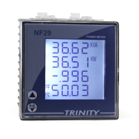
The Trinity NF29 Meter is a multi-line digital display panel meter designed to measure and display various electrical parameters. It features an RS-485 communication interface, allowing it to connect to an IoT gateway for remote data acquisition and monitoring. The TrackSo IoT Gateway, a GPRS-enabled device, acts as an intermediary, collecting data from the NF29 Meter via RS-485 and transmitting it to the TrackSo cloud platform for energy management, analysis, and reporting. This setup enables users to monitor energy consumption and other electrical metrics remotely, facilitating efficient energy management and fault detection.
*   The Trinity NF29 Meter has an RS-485 communication socket on its rear panel.
*   To connect, unscrew the RS485 terminal.
*   Connect the RS-485 cables from the Trinity NF29 Meter to the TrackSo IoT Gateway. Specifically, connect the 'A' terminal of the NF29 Meter (Pin 2) to the 'D+' terminal of the TrackSo Gateway (Pin 3), and the 'B' terminal of the NF29 Meter (Pin 1) to the 'D-' terminal of the TrackSo Gateway (Pin 4).
*   The TrackSo IoT Gateway also has connections for ANT (Antenna), SIM (SIM card slot), Rx/Tx (Receive/Transmit indicators), GSM (GSM status), and PWR (Power).
*   Push the yellow nob to release the SIM tray.
*   Pull out the SIM tray.
*   Place the SIM card into the tray.
*   Insert the SIM tray back into the SLOT and push it firmly until it clicks into place.
*   Switch on the power to the TrackSo device. A minimum 12V/1A input is required.
*   The red Power LED of the TrackSo IoT Gateway will glow and stay ON, indicating power.
*   The meter address (Modbus Address) for the RS485 port can be set from 1 to 255.
*   To enter programming mode, press the "PROG ENTR" key for 4 to 5 seconds while the meter is in Run Mode.
*   The unit will display "Addr" and the current address (e.g., "255").
*   Press the "PROG ENTR" key again. The 'P' will start blinking, indicating the parameter is settable.
*   Use the Up and Down arrow keys to set the desired Modbus Address (which should match the Inverter ID configured in the TrackSo IoT Gateway, typically 1 by default).
*   Press the "PROG ENTR" key to confirm the set value.
*   The unit will reset and return to Run Mode.
*   Multiple Trinity NF29 Meters can be connected to a single TrackSo IoT Gateway in a daisy-chain configuration via RS-485.
*   Each meter must have a unique Modbus Address (Device ID).
*   The D+ and D- lines from the TrackSo Gateway are connected to the D+ and D- terminals of the first meter, then from the first meter to the second, and so on, for all meters in the chain.
*   **POWER (Green):** Light ON when power is supplied to the device.
*   **GSM (Red):**
    *   Flashing (100ms ON/OFF): SIM Card not found.
    *   Flashing (500ms ON/OFF): Searching for GSM Network.
    *   Flashing (0.1s ON/2.9s OFF, once every 3sec): GSM Network Registered.
    *   Flashing twice every 3sec: GPRS IP Connected.
    *   Flashing 5 times: GPRS IP Sending data.
    *   LED OFF: GSM Fault.
*   **COM TX (Green):** Blinks on data transmission in RS485 port.
*   **COM RX (Yellow):** Blinks on data reception in RS485 port.
*   Send an SMS command "*2222#<Stat.gsm>" to the mobile number of the TrackSo device.
*   The device will reply with an SMS containing details like IMEI, Network (NW), Signal Strength (SIGN), GPRS connection status, PIP (TrackSo Server connection status), and LOG (number of data points stored in devices in case of no internet).
*   If the GSM light flashes 5 times (indicating GPRS IP Sending data), log in to www.trackso.in with your Username/Password.
*   Navigate to 'Units' from the menu bar.
*   Verify that the 'Status' for the relevant Unit becomes 'Receiving'.
*   If the Unit Status remains 'Not receiving' for more than 10 minutes on the TrackSo platform:
    *   Click on your email ID at the top right of the screen.
    *   Select 'Event Ingestion Logs' from the dropdown.
    *   Check if any logs are generated at the time of installation.
    *   **If NO logs:** Restart the TrackSo device and repeat the setup process.
    *   **If YES logs:** Email support@trackso.in with the log details for assistance.
*   Ensure all connections are correct as detailed in the installation guide.
*   Verify the SIM card is properly inserted and active.
*   Check the LED indicators on the TrackSo IoT Gateway to diagnose connection issues (SIM card, GSM network, GPRS IP).
*   Confirm that the Modbus Address (Device ID) configured in the Trinity NF29 Meter matches the Inverter ID set in the TrackSo IoT Gateway's default configuration.
*   Ensure the TrackSo IoT Gateway has a stable GPRS network connection at the installed location.
| Brand | Trinity |
|---|---|
| Model | NF29 |
| Category | Measuring Instruments |
| Language | English |