Do you have a question about the Trio CS-1575 and is the answer not in the manual?
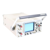
Overview of the dual trace, trigger sweep oscilloscope with 130 mm CRT and its capabilities.
Detailed technical specifications for the oscilloscope, including CRT, vertical axis, sweep, and triggering.
Specs for horizontal axis, calibrating voltage, and power supply.
Physical dimensions, weight, and included accessories of the oscilloscope.
Identification of front panel components of the oscilloscope with labels.
Diagrams showing internal component layout and their identification.
A high-level overview of the oscilloscope's internal functional blocks and their interconnections.
General explanation of the oscilloscope's various circuit sections and their functions.
Description of the vertical amplifier circuit, including preamplifiers, attenuators, and mode switching.
Explanation of the sync sweep circuit, including trigger signal shaping and saw-tooth wave generation.
Descriptions of horizontal amp, display mode, and phase display circuits.
Descriptions of dual-H, blanking, CRT power, power, and calibrating voltage circuits.
General maintenance procedures and precautions for the oscilloscope.
Instructions for safely removing the oscilloscope's case and bottom plate.
Steps for removing the CRT escutcheon or bezel without tools.
Procedure for adjusting the CRT bright line angle to align with the horizontal scale.
General guidelines and order for performing oscilloscope adjustments.
Adjustments for the power and CRT circuits, including low and high voltage supplies.
Adjustments for the CH1 vertical axis circuit, including gain, balance, and position.
Adjustments for the CH2 vertical axis circuit, including gain, balance, and position.
Vertical axis adjustments including step attenuator, position, sensitivity, and high range.
Adjustments for horizontal axis, sweep time, blanking, and input capacitance.
A troubleshooting flowchart to diagnose and resolve common oscilloscope issues.
Troubleshooting steps for pilot lamp, fuses, and power supply voltage issues.
Troubleshooting steps for spot presence, V-AMP operation, and power supply voltages.
Troubleshooting steps for bright line issues and blanking circuit malfunctions.
Troubleshooting for V-AMP operation and individual CH1/CH2 circuit issues.
Troubleshooting steps for dual trace and CHOP/ALT operation modes.
Troubleshooting for left/right dual trace and phase display functionalities.
Troubleshooting for up/down dual trace and phase display operations.
Troubleshooting for X-Y operation and phase display.
Troubleshooting steps for synchronization operations, including CH1/CH2 and EXT sync.
Troubleshooting for the blanking circuit and its associated components.
Troubleshooting steps for issues related to the calibrating voltage output.
Diagram of the main circuit board (X65-1220-00) with component layout.
Diagram of the high voltage power supply board (X68-1210-00) with component layout.
Diagram of the sweep circuit board (X74-1110-00) with component layout.
List of miscellaneous parts and resistors for model Y70-1170-00.
List of resistors for board X65-1220-00.
Continuation of parts list for X65-1220-00, including resistors, capacitors, semiconductors, and miscellaneous.
List of parts for board X68-1210-00, covering resistors, capacitors, semiconductors, and miscellaneous.
List of parts for board X74-1110-00, covering resistors, capacitors, semiconductors, and miscellaneous.
List of miscellaneous parts for board X77-1020-00.
| Model | CS-1575 |
|---|---|
| Category | Test Equipment |
| Type | Oscilloscope |
| Number of Channels | 2 |
| Trigger Modes | Auto, Norm |
| Trigger Source | CH1, CH2, LINE, EXT |
| Display | 6 inch CRT |
| Power Source | 50/60 Hz |