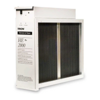
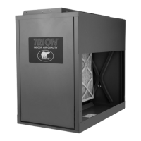
Cabinet
Mounts to existing ductwork; houses the Ionizing-Collecting Cells and Pre-filters.
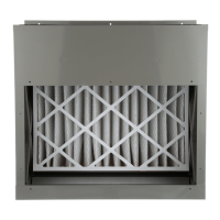
Ionizing-Collecting Cells
Collect the dust, dirt and other particulates in the air. They contain the ionizing and collecting sections.
The cells must be installed with the ionizing wires on the air intake side. A spring contact is located on
the top of each cell and must be in the position to make contact with the contact board assemblies on
the bottom of the Power Tray Assembly.
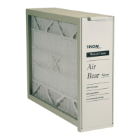
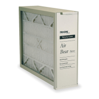
Pre-filters
Trap large particulates before they enter the Ionizing-Collecting Cell.
Power Tray Assembly
Contains the indicating lights, solid-state power supply, contact boards and electrical controls including
the ON/OFF switch and safety interlock switch. A power cord at the rear of the 120 volt Power Tray
allows the unit to be connected to a standard 120 volt outlet. A wiring compartment is provided on all
models at the rear of the Power Tray allowing the option to permanently wire the unit directly to the
HVAC System Control.
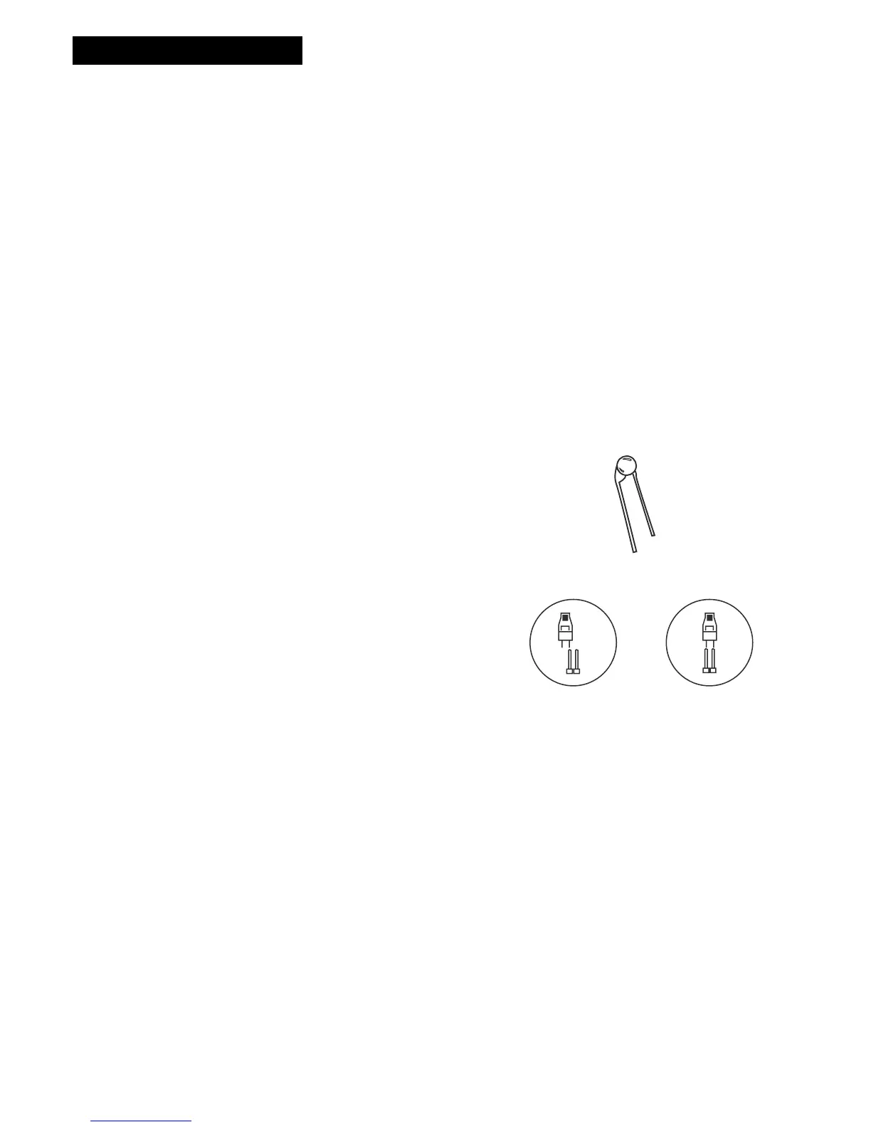
Air Flow Sensor (AFS)
Controls the operation of the unit by sensing the movement
of air within the duct. This helps to reduce power usage.
How the AirFlow Sensor Works
Electronic AFS was designed to provide an efficient and
reliable method of controlling the operation of the air
cleaner when the dealer is unable to wire the unit directly
into the furnace blower. The electronic AFS is now
integrated into the power supply circuitry and utilizes a
thermistor that heats up to approximately 130°F. The AFS
then stabilizes at this temperature and when the furnace
blower turns on and air flows through the ductwork, the
same vacuum effect pulls cooler air over the hot surface.
This air movement cools down the thermistor and this
cooling down effect allows the electronic AFS to understand
that the furnace blower is moving air and the Electronic Air
Cleaner must turn on to provide air cleaning. If the air
cleaner is installed in a location that is dusty and dirty, the
sensor on the AFS can become coated with dirt and lint.
This coating can insulate the AFS and keep it from
operating properly. To clean the thermistor,
turn unit off
and allow thermistor to cool, then take a cotton swab dipped
in rubbing alcohol and carefully insert it into the hole located
on the right hand side of the power pack assembly (when
facing the unit). The hole is 3/16” in diameter and is located
on the front of the power tray assembly
. Carefully twirl the
cotton swab between your fingers, making sure the tip is
lightly in contact with the coated bead, cleaning this coating
from the thermistor. If airflow sensor is bypassed on the
circuit board, the Air Cleaner will run at all times when
power is applied.
Unit Components
2