12
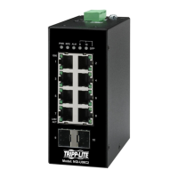
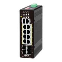
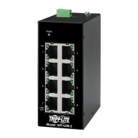
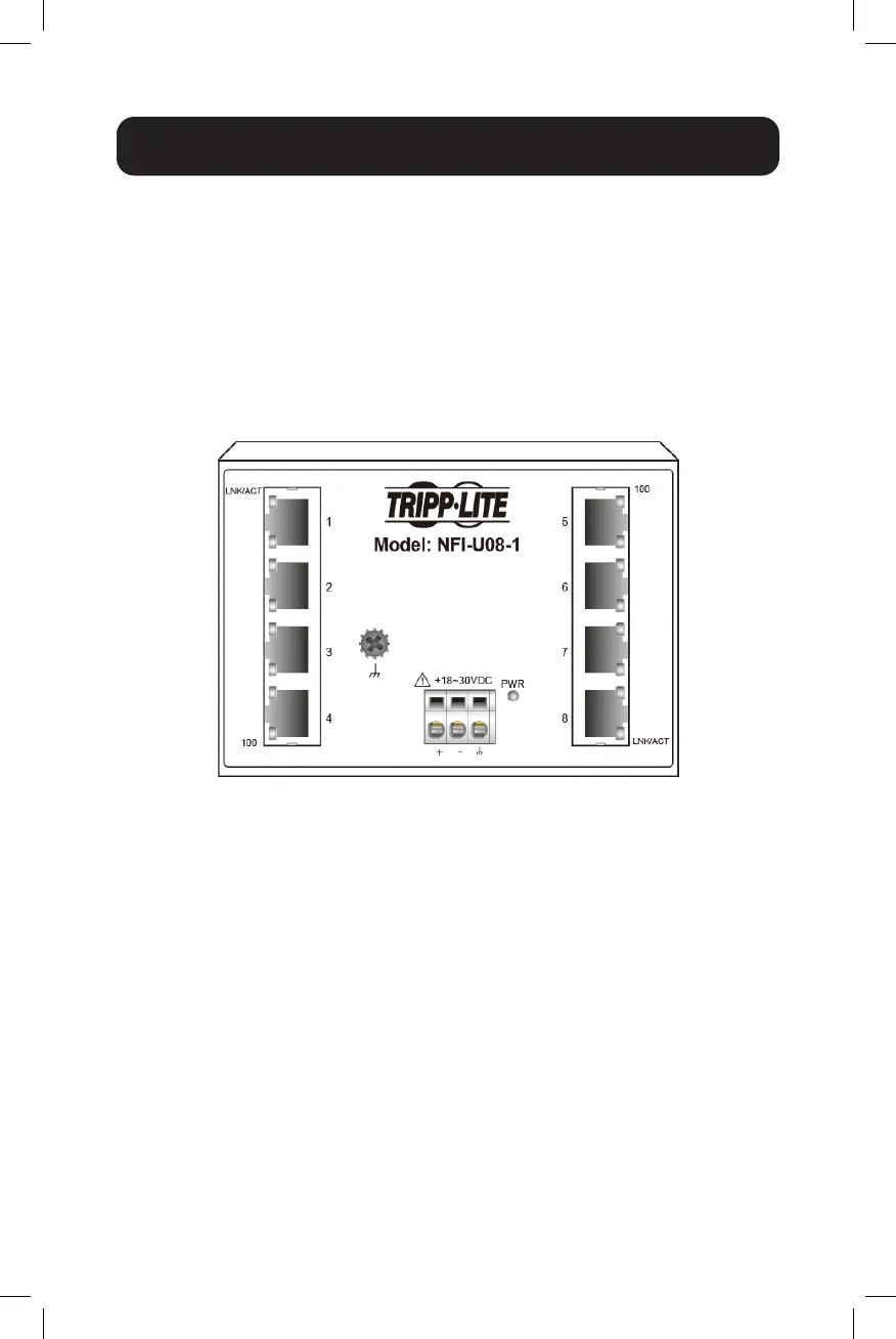
NFI-U08-1 with 3-Pin Terminal Block
Note: The 3-Pin Terminal Block is integrated to switch case. The NFI-U08-1 is
designed to face forward and requires more space. It utilizes a different type of
terminal block (gray color) commonly known as a PCB terminal block, as it is directly
mounted in the PCBA. The NFI-U08-1 model does not require an additional male
connector like the NFI-U05 and NFI-U08-2 models.
Check the polarity while connecting. Top view of the Terminal Block is shown
in the figure below:
Wiring Requirements
CAUTION:
• Use copper conductors only.
• Wiring cable temperature should support at least 105˚C (221˚F).
• T
he wire gauge for the terminal block should range between 12~22 AWG.
To insert the power wire and connect the 18~30V DC at a maximum of
0.5A DC power to the power terminal block, follow the steps below:
• Use a flathead screwdriver to push in and open the wire clamp.
• Insert the negative/positive DC wires into the ( - / +) terminals,
respectively.
• Tighten the wire clamp by releasing the screwdriver to prevent the wires
from loosening.
ATTENTION: Use a power supply from 18~30V DC. The device power shall
be supplied by SELV circuit.
 Loading...