13
Wiring Requirements
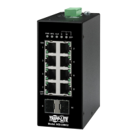
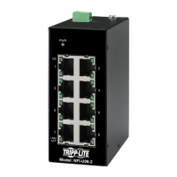
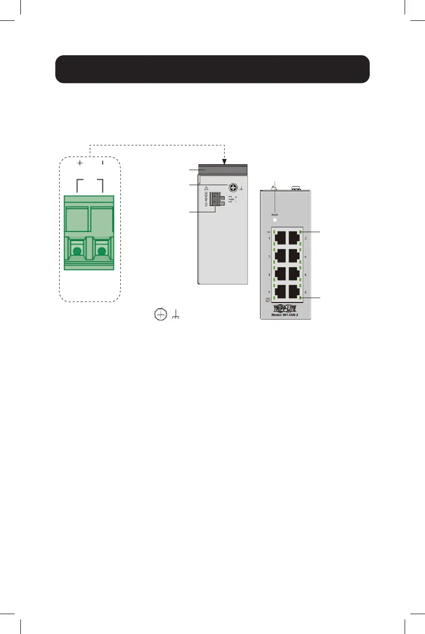
NFI-U08-2 with 2-Pin Terminal Block
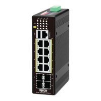
You can use “PWR” for Power input. Top view of the Terminal Block is shown
in the figure below:
CAUTION:
• Use copper conductors only.
• Wiring cable temperature should support at least 105°C (221˚F).
• Tighten the wire to a torque value 0.5 N•m (4.5 in•lb).
Note: The NFI-U08-2 wire gauge for the terminal block should range between 12
and 24 AWG. Power input is 18~30VDC at a maximum of 0.2A DC power.
To insert power wire and connect the 12~48VDC at a maximum of
0.2A DC power to the power terminal block, follow these steps:
• Use a flat-head screwdriver to loosen the wire-clamp screws.
• Insert the negative/positive DC wires into the PWR-/PWR+ terminals,
respectively.
• Tighten the wire-clamp screws to prevent the wires from loosening.
ATTENTION: Use a power supply from 12~48VDC. The device power shall
be supplied by 61010-2-301 R/C power with SELV, Limited energy output.
Terminal
Block
PWR
DIN Rail
Grounding
Screw
Power Input
Terminal Block
Top View
Front View
100 Mbps
LNK/ACT
Grounding
Screw
PWR
 Loading...