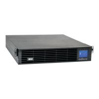
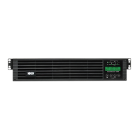
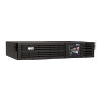
EasyManua.ls Logo

Tripp Lite SmartOnline SU10KRT3/1X User Manual

Tripp Lite SmartOnline SU10KRT3/1X
76 pages
To Next Page IconTo Next Page
Page #1 background imageLoading...
Page #1 background image
1
Owner’s Manual
SU10KRT3/1X
SmartOnline
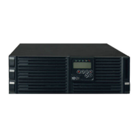
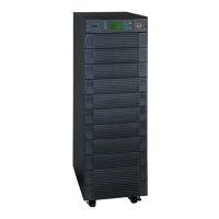
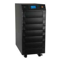
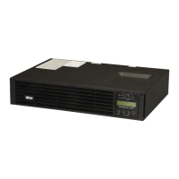
Rack/Tower On-Line UPS System
with Parallel Redundancy Capability
Input: 160-280/277-485V AC, 50/60 Hz, 3Ø, 4-Wire + Ground, Wye
Output: User-Selectable 200/220/230/240V AC, 50/60 Hz, 1Ø, 2-Wire + Ground
Not suitable for mobile applications.
1111 W. 35th Street, Chicago, IL 60609 USA
+1.773.869.1234 • www.tripplite.com
Copyright © 2009 Tripp Lite. SmartOnline is a trademark of Tripp Lite. All other trademarks are the sole property of their respective owners.
1 – Introduction 2
2 – Important Safety Instructions 2
3 – Rear Panel Features 4
4 – Mounting 5
4-1 Unpacking 5
4-2 Placement 6
4-3 Mounting (Rack) 6
4-4 Mounting (Tower) 7
5 – Wiring 7
5-1 Wiring Preparation 7
5-2 Terminal Block Diagram 7
5-3 Electrical and Cable Data 8
5-4 AC Input/Output Wiring Instructions 8
5-5 External Battery Pack Connection 9
6 – Standard Operation 10
6-1 Control Panel Features 10
6-2 Control Panel Error Codes 11
6-3 Normal Mode Startup 12
6-4 Battery Mode Startup (Cold Start) 13
6-5 UPS System Shutdown 13
6-6 UPS System Settings and Measurements 13
7 – Parallel Redundancy Operation 15
8 – Communications 16
8-1 Network Card 16
8-2 EPO Connection 16
8-3 RS-232 Serial Communications 16
9 – Troubleshooting 17
10 – Specifications 18
11 – Storage and Service 18
12 – Warranty 19
Español 20
Français 39
Русский
58

Table of Contents

Questions and Answers:

Tripp Lite SmartOnline SU10KRT3/1X Specifications

General IconGeneral
BrandTripp Lite
ModelSmartOnline SU10KRT3/1X
CategoryUPS
LanguageEnglish

Summary

Introduction

Safety Instructions

Location Warnings

Warnings about where to install the UPS for safe operation and optimal performance.

Connection Warnings

Critical warnings regarding electrical connections and user safety during installation.

Wiring Warnings

Essential safety precautions and guidelines for electrical wiring of the UPS system.

Battery Warnings

Safety precautions and handling instructions for UPS batteries to prevent injury and damage.

Labeling and Symbols

Explanation of symbols found on the product label for identification.

Rear Panel Features

UPS System Power Module Rear Panel

Identifies and describes the ports and connectors on the rear of the UPS power module.

Mounting

4-1 Unpacking

Instructions for unpacking the UPS system and checking the packing list.

UPS System Hardware Kit

Details the components included in the UPS system hardware kit for installation.

4-2 Placement

Guidance on selecting an appropriate location for the UPS system to ensure optimal performance.

4-3 Rack Mounting Procedures

Detailed procedure for mounting the UPS system in a 4-post rack or enclosure.

4-4 Tower Mounting Procedure

Instructions for mounting the UPS system in an upright, tower configuration.

Wiring

5-1 Wiring Preparation

Steps to prepare for wiring, including de-energizing and marking cables.

5-2 Terminal Block Diagram

Illustrates the terminal block layout for AC input and output connections.

5-3 Electrical and Cable Data

Provides specifications for AC input/output wiring, including current, diameter, and torque.

5-4 AC Input/Output Wiring Instructions

Step-by-step instructions for connecting AC input and output wiring.

5-5 External Battery Pack Connection

Procedure for connecting an external battery pack to the UPS system.

Standard Operation

Control Panel Features and Diagnostics

Overview of control panel, buttons, LEDs, LCD symbols, and error codes for operation.

Normal Mode Startup

Step-by-step guide for starting the UPS system in normal operating mode.

Battery Mode Startup (Cold Start)

Instructions for starting the UPS from battery power when AC input is unavailable.

UPS System Shutdown

Procedures for safely shutting down the UPS system and its output.

System Settings and Configuration

How to check measurements, access settings, and change defaults.

Parallel Redundancy Operation

Parallel Kit Contents and Placement

Lists parallel kit components and guidelines for UPS system placement.

Parallel Installation and Startup

Procedure for installing and starting up UPS systems in parallel mode.

Communications

Network Card for Remote Monitoring

Information about the internal network card for remote monitoring and control.

EPO and RS-232 Serial Communications

How to use EPO and connect via RS-232 serial port for monitoring.

Troubleshooting

Problem Resolution Guide

Table listing common problems, error codes, and possible solutions for the UPS system.

Releasing UPS System Lock

How to handle errors detected during the UPS self-test procedure.

Specifications

Input and Output Specifications

Technical specifications for the UPS input and output power requirements.

Physical Dimensions and Weight

Physical dimensions and weight of the UPS power module.

Storage and Service

Storage Guidelines

Guidelines for storing the UPS system to maintain battery health.

Service and Warranty Information

Information on warranty, service options, and contacting support.

Warranty Information

Limited Warranty Terms

Terms and conditions of the product's limited warranty.

Regulatory Compliance and Identification

Information on compliance numbers and product identification.

Related product manuals