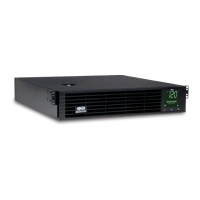
Do you have a question about the Tripp Lite SmartPro SMART500RT1U and is the answer not in the manual?
| Form Factor | 1U Rackmount |
|---|---|
| Output Voltage Regulation | ±5% |
| Input Frequency | 50/60 Hz |
| Output Frequency | 50/60 Hz |
| Waveform Type | Sine Wave |
| Transfer Time | 2-4 ms |
| Operating Humidity | 0% to 95% non-condensing |
| Power Capacity | 500 VA |
| Output Power | 300 W |
| Input Voltage | 120V |
| Output Voltage | 120V |
| Battery Type | Sealed Lead Acid (SLA) |
| Input Voltage Range | 90-140V |
| Interface Port | USB |
| Operating Temperature | 32°F to 104°F (0°C to 40°C) |
| Certifications | cUL, FCC |
| Number of Outlets | 6 (5 x 5-15R; 1 x 5-15P) |
Warnings for placing UPS indoors, away from heat, dust, sunlight, and ensuring proper ventilation space around vents.
Instructions regarding UPS power source, proper grounding, generator connections, and avoiding self-connection.
Cautions against using UPS for life support and connecting surge protectors or extension cords to UPS output.
Guidelines on battery maintenance, risk of electrical shock, proper replacement, and disposal of batteries.
Instructions for mounting UPS in a 4-post rack using included hardware and optional shelf kit.
Procedures for mounting 1U UPS in 2-post racks, noting the need for a separate kit for 2U models.
Instructions for mounting UPS in an upright tower position using included hardware.
Connecting UPS to a computer for software monitoring and control via USB or serial cable.
Connecting UPS to a facility's EPO circuit for emergency shutdown via a normally closed/open switch.
Connecting optional external battery packs to select models for extended runtime.
How to use the POWER and MUTE/TEST buttons for UPS control and self-testing.
Explanation of the status indicated by various LEDs on the front panel.
Details on AC receptacles, communication ports (USB/RS-232), and EPO port on the rear.
Covers accessory slot, sensitivity adjustment, breakers, ground screw, and external battery connector.
Proper methods for storing the UPS, including battery recharge intervals to maintain capacity.
Steps for troubleshooting, contacting support, and returning the UPS for warranty service.