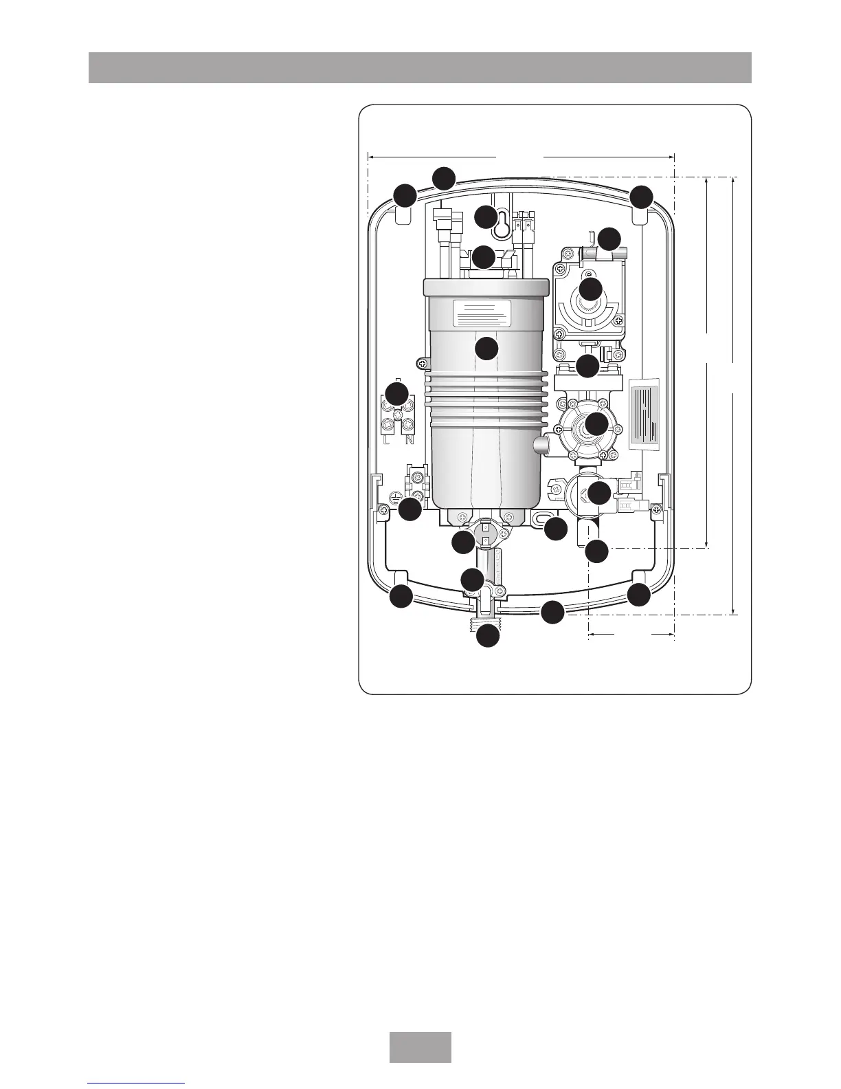
EasyManuals Logo

Triton Forte User Manual

Triton Forte
25 pages
To Next Page IconTo Next Page
To Previous Page IconTo Previous Page
Page #5 background imageLoading...
Page #5 background image
3
Forte
MAIN COMPONENTS
Inside unit (fig.1)
1. Top cable/pipe entry
2. Wall screw fixings
3. Cover screw fixings
4. Thermal safety cut-out (main)
5. Power selector assembly
6. Power neon
7. Can and element assembly
8. Pressure switch assembly
9. Stabilising valve
10. Terminal block
11. Earth connection
12. Solenoid valve
13. Water inlet
14. Outlet temperature limiter
15. Pressure relief device (PRD)
16. Trimplate
17. Shower outlet
Pack contents
Shower unit
Screw fixing kit
Instructions, guarantee, etc.
255
mm
305
mm
210 mm
59 mm
Fig.1
NOTE: Not all wiring has been shown for reasons of clarity.
1
2
3
4
6
7
8
9
10
11
12
13141516
3
17
15
14
13
2
3
3
5

Questions and Answers:

Question and Answer IconNeed help?

Do you have a question about the Triton Forte and is the answer not in the manual?

Triton Forte Specifications

General IconGeneral
BrandTriton
ModelForte
CategoryPlumbing Product
LanguageEnglish

Related product manuals