9
6. Return the router to a normal operating depth. This will disengage the
collet lock and release the retracting switch shutter, enabling access to the
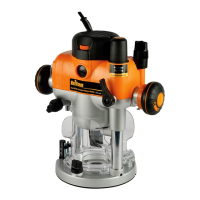
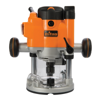
Power Switch (12)
Dust extraction port
Note: The Triton Router is equipped with a Dust Extraction Port (18) for chip
extraction above the cut. The Dust Extraction Port accepts 38mm outer-
diameter hose. It is also compatible with the Triton Dust Collector (DCA300)
and the Triton Dust Port Adaptor (TDPADIN) which allows for third-party hoses
to be attached.
• The dust extraction hose screws into position via a left-hand thread (anti-
clockwise)
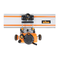
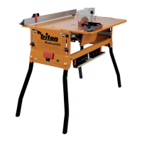
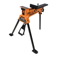
Extended baseplate and fence installation
Note: When using the router with the baseplate fitted, place one hand on
the long end of the base, holding it down onto your work, and grip the router
handle, furthest away, with your other hand.
1. Locate the two Baseplate Mounting Knobs (20) and loosen them entirely.
This permits the mounting studs to engage the router securing holes on the
Extended Baseplate (24)
2. Turn both the plunge router and the Extended Baseplate upside down
3. Press the Baseplate Mounting Knobs on the plunge router inwards, to
expose the mounting studs
4. Align the mounting studs with the router securing holes on the Extended
Baseplate (24), and slide into the keyhole slots (image E).
Note: The extended baseplate orientation is dependent on where the support
is required. For edge work, locate the Power Switch (12) on the short overhang
side of the base
5. Tighten the Baseplate Mounting Knobs on the plunge router firmly to
secure the plunge router to the Extended Baseplate
6. To fit the Fence (21) loosen the fence knobs, and slide the fence along the
tracks on the Extended Baseplate (image F). Lock at the required setting by
tightening both fence knobs
Note: When routing trenches at distance from an edge, fit the fence to the long
end of the baseplate.
Note: When performing edge work with a non-bearing guided cutter, fit the
fence to the short end of the baseplate, (image G)
Note: If using a very large diameter cutter it may be necessary to fix wooden
blocks to the fence faces via the screw holes, to ensure the cutter does not
contact the fence.
Operation
WARNING: ALWAYS wear eye protection, adequate respiratory and hearing
protection, as well as suitable gloves, when working with this tool.
Switching on and off
Note: When the router is connected to the power source, the Power Switch (12)
will illuminate in both ‘On’ and ‘Off’ positions.
Note: The Retracting Power Switch Cover (13) prevents accidental starting of
the router. It must be retracted before the router can be switched on (image A).
The cover will remain open until the router is switched off.
1. Ensure that the plunge router is at the maximum extension of its travel, and
that the cutter will not conflict with any foreign objects when it is powered
on
2. Connect the power cord to the mains, and slide the Retracting Power
Switch Cover back to reveal the Power Switch
3. Press the Power Switch in the ‘I’ position to turn the plunge router ON
(image B). Whilst the Power Switch is in this position, the Retracting Power
Switch Cover will be prevented from re-covering the Power Switch
4. To turn OFF, press the Power Switch in the ‘O’ position. The Retracting
Power Switch Cover will slide back to its original position
Variable speed control
Note: Router speed settings are not critical. Generally the highest speed which
does not result in burn marks on the workpiece should be used. Where stated,
always follow the cutter manufacturers’ maximum speed limitations.
• Operating at reduced speed increases the risk of damage to the router as a
result of overload. Use very slow feed rates and/or multiple shallow cuts.
• The Speed Controller (15) is marked 1 to 5, corresponding approximately
with the speeds and cutter diameters below. Turn the dial to select the
required speed (image H)
Setting RPM Cutter Diameter
5 21,000 Up to 25mm
4 18,000 25-50mm
3 14,500 50-65mm
2 11,000 Over 65mm
1 8000 Use only if burning
Cutting depth adjustment
Note: To lock the router at a particular depth of cut, plunge the router head
down and rotate the Plunge Lock Lever (16) to its lower position. This will hold
the router head in this position
• There are three methods of cut depth adjustment, depending on the
accuracy and control required:
Free plunge
1. Free plunge depth adjustments can be made with the Plunge Selection
Button (6) engaged. Press the Plunge Selection Button deep inside the
handle until it engages inward (image I)
2. Release the Plunge Lock Lever (16) and push the body of the router until
the required depth is reached. Re-lock the Plunge Lock Lever
Note: The position of the Plunge Lock Lever can be altered by removing its
retaining screw and repositioning the lever on the bolt. Re-tighten firmly.
Table Height Winder
1. Plunge depth adjustments can be made by turning the Winder Handle (7)
2. Disengage the Plunge Selection Button (6) and ensure that the button is
flush with the Winder Handle (image J)
3. To release the handle, pull the Winder Handle Clutch Ring (8) inwards
4. Release the Plunge Lock Lever (16) and twist the Winder Handle until the
desired depth of cut is reached. Release the Winder Handle Clutch Ring,
and lock the Plunge Lock Lever
Micro Winder
Note: For use in Winder Handle (7) plunge mode only.
1. Disengage the Plunge Selection Button (6), and ensure that the Plunge
Lock Lever (16) is unlocked
Note: If the Micro Winder (10) is turned with the Plunge Lock Lever engaged,
the Micro Winder will start clicking and the cut depth will remain unchanged.
2. Turn the Micro Winder clockwise to increase cut depth and anti-clockwise
to reduce cut depth. Adjust the cut depth until the desired height is reached
(image K)
Note: When the end of the depth adjustment range is reached, the Micro
Winder will offer greater resistance and will begin to ‘click’.
3. Engage the Plunge Lock Lever, particularly for heavy cuts
Depth stop and turret
1. The Depth Stop (4) and Turret Stops (1) are used to accurately pre-set up to
three different cut depths.
2. Loosen the Depth Stop Lock Knob (5) and retract the Depth Stop (4) fully,
then re-tighten (image L)
3. Set the turret posts to the required plunge depths using the scales on the
stationary turret post (image M)
Note: To change turret posts, rotate the entire turret assembly to align with the
Depth Stop (image N)
4. With the desired cutter installed into the Collet (22), adjust the plunge
depth until the tip of the cutter touches the workpiece
5. Rotate the turret until the fixed turret post is in line with the Depth Stop.
Release the stop, allowing it to spring onto the post, then re-tighten the
Depth Stop Lock Knob. The plunge depth is now set at zero (image O)
6. Rotate the Turret Stops until the turret post with the desired plunge depth is
aligned with the Depth Stop
813291_Z1MANPRO1_AUS.indd 5 13/12/2016 08:54

 Loading...