22
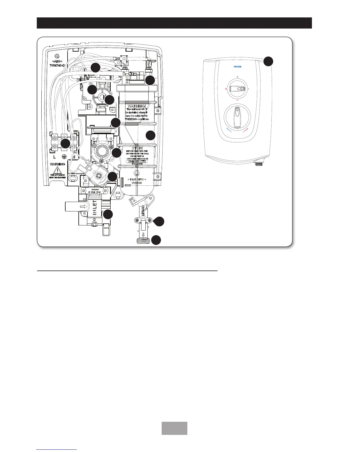
SPARE PARTS
1
2
3
5
8
9
10
6
4
11
Ref. Description Part No. Model
1. Inlet lter assembly ...................P22611004
2. Solenoid Valve ..........................P22610801
3. Stabilising Valve ........................P22640800
4. Pressure Switch Module ............P22611003
5. Can & Element Assembly .........83314800 (8.5kW)
................................................83314810 (9.5kW)
83314820 (10.5kW)
6. Outlet Pipe and PRD .................S85000310
7. Terminal Block and wires ..........S82201240
8. Thermal Cut-Out (TCO) ...........22012340
9. Microswitch (X2) ......................83314240
10. Cover Assembly ........................P80000076
11. Pressure Relief Device (PRD) .....82800450
12. Switch carriage top ..................P22611001
13. On/Off microswitch .................. 22012460
7
12
13
 Loading...