10
Making multiple pass cuts
1. The Turret Stops (1) allow the maximum depth of cut to be achieved in an operator-
determined number of steps. Each step of the turret can be pre-set by adjusting the
thumbwheel on the turret post
2. Rotate the Turret Stops so that the Depth Stop will contact the highest pre-set turret post
when the router is plunged. The first pass of the cut can now be made
3. Continue to make passes, rotating the Turret Stops and adjusting the turret post depth for
each pass when necessary until the full depth of cut has been achieved
Circle Cutting
1. Fit the Extended Baseplate (27), without the Fence (22) attachment, to the router
2. Remove the Circle Cutting Pivot Mount (26) from the Extended Baseplate and fix it to the
centre of the workpiece, using a small nail or screw, through one of the holes in the pivot
mount, (Image M). Leave the pivot mount bolt in position
3. Lower the router and base over the pivot mount and refit the washer and wing-nut,
(Image N)
4. With the power switched ‘Off’, rotate the router along the intended path to check the
circle, and make any necessary adjustments
5. Cut the circle in several passes, lowering the cut depth by approximately 2mm (3/32")
each pass, (Image N). Do not attempt to cut deeply in one pass
• Through cuts: If cutting all the way through the material, fix a sacrificial board to the
underneath of the workpiece. Cut the circle oversize, then when the cut is all the way
through, reduce the diameter and work back to the required size, using light, full depth
passes
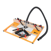
Table-mounted operation
WARNING: When in use with the Triton Workcentre Router Table Module TWX7RT001,
the maximum cutter Dia. Is 50mm. This is constrained by the Workcentre specification.
Note: Fitting and operating this router on a router table should be carried out in accordance
with the literature supplied with the router table.
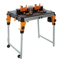
Note: Whilst this product was designed for efficient and convenient operation on most router
tables, it is particularly suited for use with the Triton Router Table RTA300 and TWX7RT001.
Note: Router adjustments are extremely easy using the unique features described
earlier in the manual. See ‘Collet and cutter installation’ and ‘Cut Depth Adjustment’.
Note: The plunge spring MUST be removed before this router is fitted into a router table:
1. Set the router at the top of its plunge range and engage the Plunge Lock Lever (11)
2. Loosen the small screw next to the Plunge Spring Access Cap (21) a few turns
3. Holding the Plunge Spring Access Cap firmly so that the spring will not shoot upwards
when released, twist the cap anti-clockwise to remove it, (Image O)
4. Remove the spring and store in a safe place
5. Replace the Plunge Spring Access Cap and re-tighten the screw
NOTE: Be sure to re-fit the plunge spring before using the router freehand.
IMPORTANT: Before mounting the router under the router table, make sure the Depth Stop
Lock Knob (5) is loosened and the Plunge Lock Level (11) is in the unlocked position.
• The Table Height Winder (24) engages with the Table Height Winder Connection Point (14)
for quick and easy above-the-table height adjustment when the router is table-mounted
Accessing the baseplate screw threads
1. To mount the router in a third-party router table or a table of your own construction
remove the 4 x screws of the baseplate indicated in Image Q and remove the baseplate
2. There are 2 sets of screw threads as shown in fig. II. There are 4 x ¼ UNC screw threads
(A) which are used to secure the baseplate as well as suitable for table mounting plus an
alternate set of 3 x M6 threads (B)
Note: The M6 threads are not available on earlier versions of the TRA001 router.
Accessories
• A wide range of suitable accessories for this tool are available from your Triton stockist,
including a large selection of cutter/router bits. Spares including carbon brushes, guide
bushes and collets are available from your Triton stockist or www.toolsparesonline.com
Maintenance
WARNING: ALWAYS disconnect from the power supply before carrying out any inspection,
maintenance or cleaning.
General Inspection
• Regularly check that all the fixing screws are tight
• Inspect the supply cord of the tool, prior to each use, for damage or wear. Repairs should
be carried out by an authorised Triton service centre. This advice also applies to extension
cords used with this tool
Cleaning
WARNING: ALWAYS wear protective equipment including eye protection and gloves when
cleaning this tool.
• Keep your tool clean at all times. Dirt and dust will cause internal parts to wear quickly,
and shorten the device’s service life
• Clean the body of your machine with a soft brush, or dry cloth
• Never use caustic agents to clean plastic parts. If dry cleaning is not sufficient, a mild
detergent on a damp cloth is recommended
• Water must never come into contact with the tool
• Ensure the tool is thoroughly dry before using it
• If available, use clean, dry, compressed air to blow through the ventilation holes
(where applicable)
Lubrication
• Slightly lubricate all moving parts at regular intervals with a suitable spray lubricant
Brushes
• Over time the carbon brushes inside the motor may become worn
• Excessively worn brushes may cause loss of power, intermittent failure, or visible sparking
• To replace the brushes, remove the two Brush Access Covers (9). Carefully remove the
worn brushes (Image P) and ensure the sockets are clean. Carefully replace with new
brushes and then replace the Brush Access Covers
• After fitting run the router without load for 2-3 minutes to help the brushes bed in. The
process of the brushes fully bedding in may take repeated uses. Motor sparking may
continue until new carbon brushes have bedded in
• Alternatively, have the machine serviced at an authorised service centre
Contact
For technical or repair service advice, please contact the
helpline on (+44) 1935 382 222
Web: tritontools.com/en-GB/Support
UK Address:
Toolstream Ltd.
Boundary Way
Lufton Trading Estate
Yeovil, Somerset
BA22 8HZ, United Kingdom
EU Address:
Toolstream B.V.
De Keten
00004
5651 GJ
Eindhoven, Netherlands
Storage
• Store this tool carefully in a secure, dry place out of the reach of children
Disposal
Always adhere to national regulations when disposing of power tools
that are no longer functional and are not viable for repair.
• Do not dispose of power tools, or other waste electrical and electronic equipment (WEEE),
with household waste
• Contact your local waste disposal authority for information on the correct way to dispose
of power tools
330165_OwnerManual_08JUL21 .indd 10330165_OwnerManual_08JUL21 .indd 10 09/07/2021 09:1609/07/2021 09:16

 Loading...