ASSEMBLY STEPS
STEP 06
Insert the PEDAL (13 L), PEDAL (14R) to the CRANK ( Mark “L” for the
left side, and mark “R” for the right side)
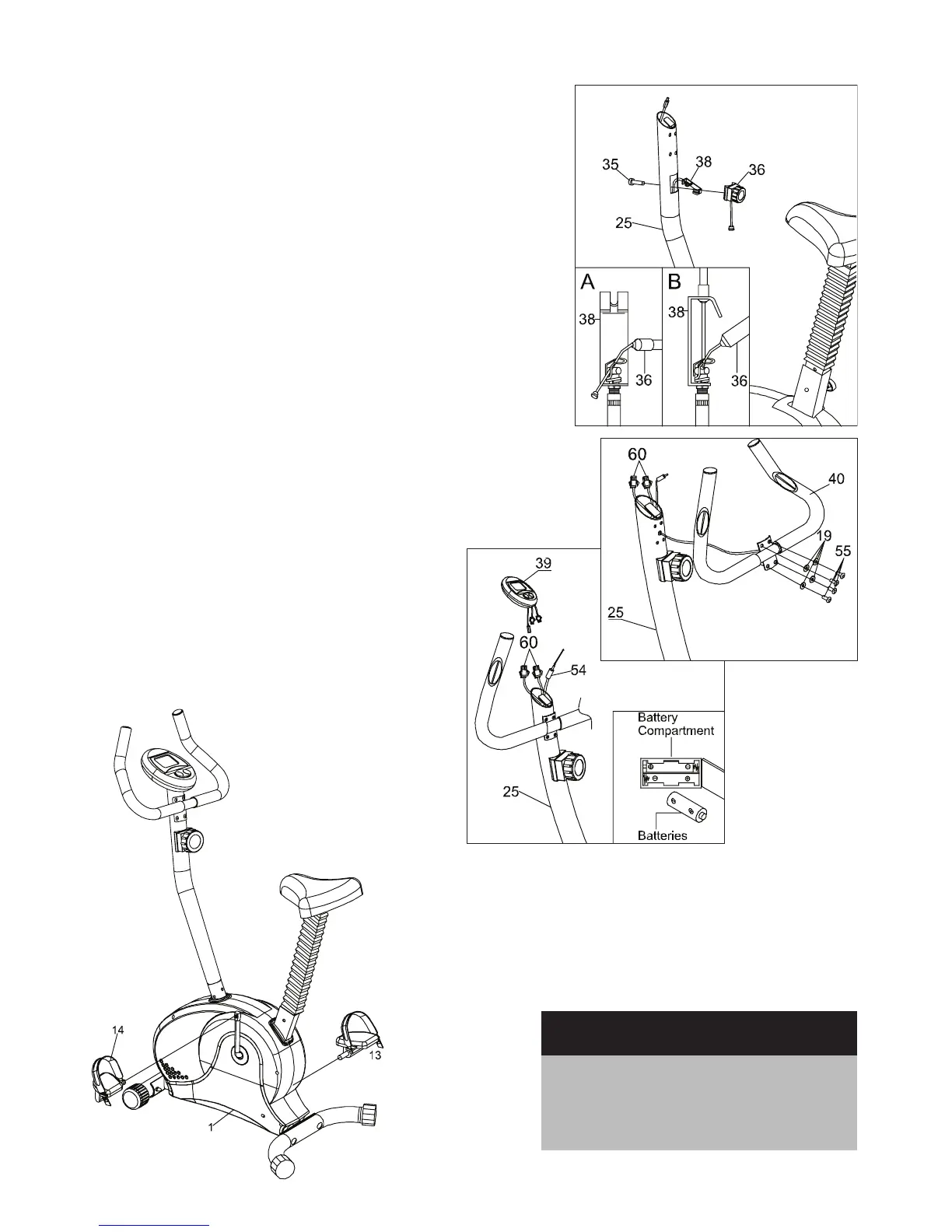
STEP 04
•GettheTensionCable(38)outoftheHandlebarTube(40)hole,and
connectittotheTensionController(36)asshowningAandgB.
Fig A : Put the Cable (36) end into the spring hook.
Fig B : Pull the knob and force the short Cable (36) into the gap of the
bracket.
•InserttheTensionKnob(36)intotheHandlebarPost(25),andattach
with Screw (35). Tension is increased by turning the Tension Knob (36)
clockwise, and decreased by turning the Knob counterclockwise
STEP 05
•AttachtheHandlebar(40)totheUprightPost(25)withScrews(55)
and Washers (19).
•InserttheWires(60)intothebiggerholeandpullthemoutfromthe
top of the Upright Post (25).
•Openthebatterycoveronthebackofthe
computer, and install 2 AA batteries.
•ConnectthemaleendofSensorLine(54)tothe
Computer (39) and connect the Wires (60) on the
Computer (39) respectively. Attach Computer (39)
onto the Upright Post (25).
CAUTION:
Ensure that cables are not
damaged during assembly or
when tightening screws.