4. ASSEMBLY STEPS
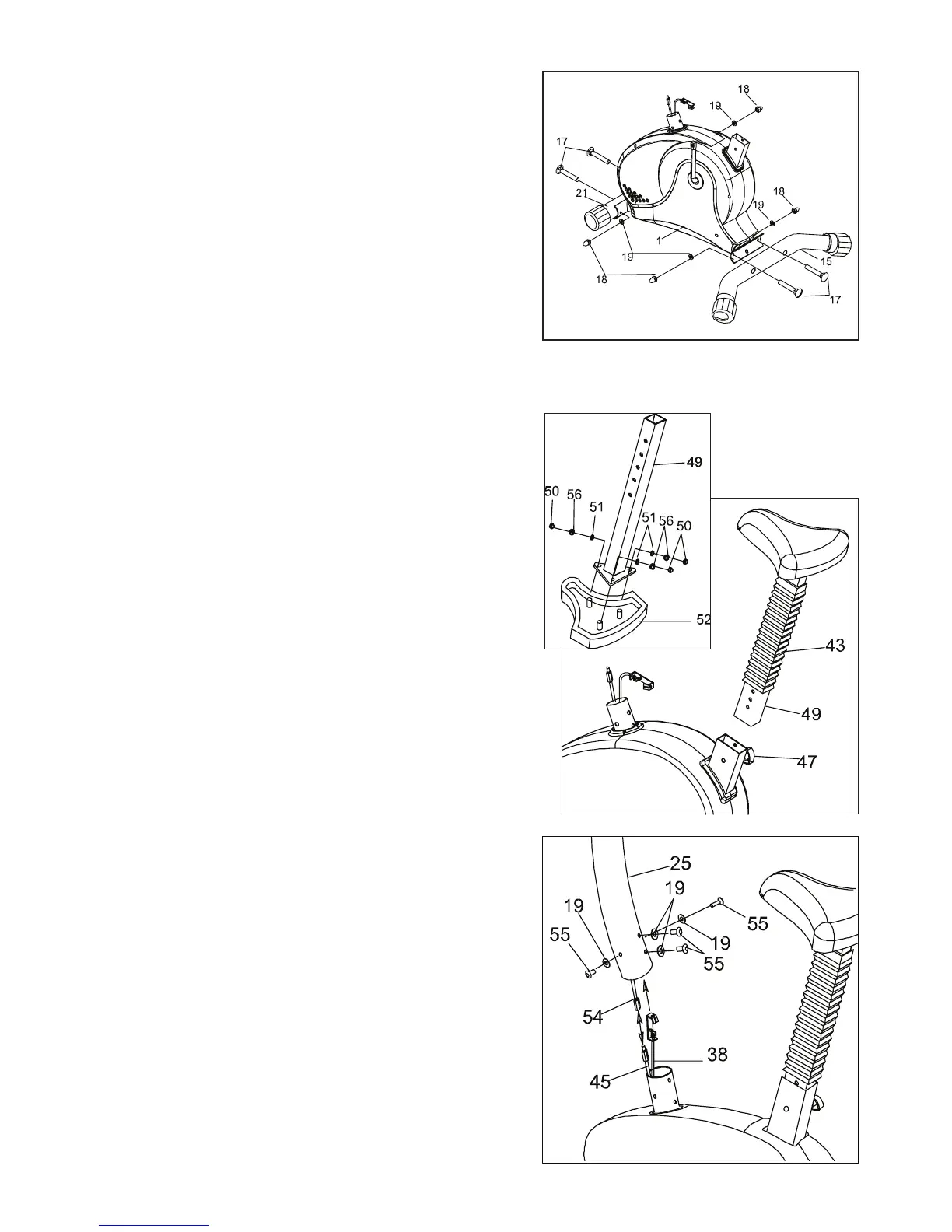
STEP 01
•AttachtheFrontStabilizer(21)andtheRearStabilizer(15)to
Mainframe (1) with Carriage Bolts (17), Washers (19) and
Cap Nuts (18).
STEP 03
•ConnecttheSensorCable(54)totheSensorCable(45)onthe
Mainframe (1).
•PulltheTensionCable(38)slowlyandinsertitupintoHandlebar
Post (25).
•AttachtheHandlebarPost(25)withScrews(55)and
Arc Washers (19).
CAUTION:
Ensure that cables are not damaged
during assembly or when tightening screws.
STEP 02
•AssembletheSeat(52)totheSeatTube(49)withattachedNylon
Nuts & Washers (50, 56, 51).
•PulltheSeatTube(49)throughthePlasticBellows(43).
•InserttheSeatTube(49)intotheMainframe(1).
•SetitatthedesiredheightwiththeSeatKnob(47).