13
ASSEMBLY STEPS
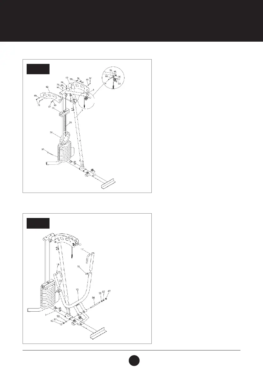
STEP 3:
Lift the Top Plate (30) and Weight Selection
Rod (29) up, then slide the 10 Weight Plates
(31) into place, 1 at a time.
Insert the Weight Selection Pin (33) into the
desired Weight Plate.
Place the Upper Cable (63) in the groove
of the Red Pulley( 53) and install the Red
Pulley (53) into the bracket of the Top
Beam (5) using 1 Hex Bolt (3/8” x 2”) (74),
2 Washers (3/8”) (90) and 1 Locknut (3/8”)
(85).
Attach the Top Beam (5) to the top of the
Guide Rods (4) using 2 Hex Bolts (3/8” x 1”)
(16) and 2 (3/8”) Washers (90). Place the
Top Beam (5) onto the Vertical Post (3).
Attach 2 Plirtes ( 62) to the Top Beam (5)
using 2 (3/8” x 4-1 /4”) Hex Bolts (71), 2 Allen
Bolts (3/8” x 3/4”) (97), 6 Washers (3/8”)
(90) and 2 Locknuts (3/8”) (85).
STEP 3
STEP 4:
Attach the Bench Press Arm (13) to the
Main Base (1) using 1 Pivot Shaft (Ø19 x 280
mm) (84), 2 Washers (5/8”) (92), 2 Locknuts
(5/8”) (87) and 2 Plastic Dome Caps (5/8”)
(43).
Insert the Adjustable Press Frame A & B
(17, 18) into the Bench Press Arm (13) using
Pop Pins (PT-1B ) (51) to secure them in
place.
STEP 4