14
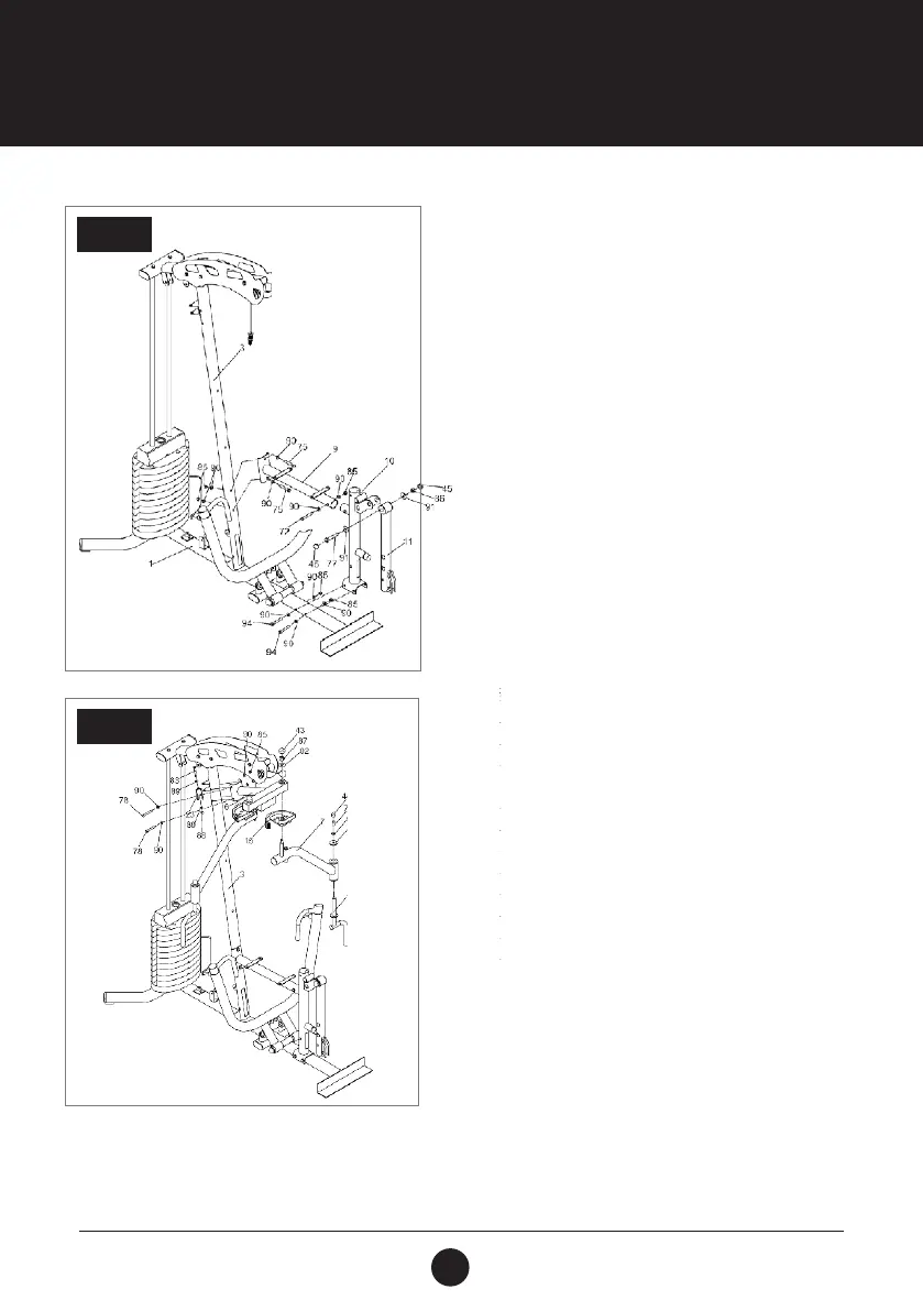
STEP 5:
Attach the Seat Cushion Support (9) to the Seat
Support Post (10) using 1 Hex Bolt (3/8” x 2-1/2”)
(72), 2 Washers (3/8”) (90) and 1 Locknut (3/8”)
(85),
Attach the Seat Cushion Support (9) to the Vertical
Post (3) using 2 Hex Bolts (3/8” x 2-1/8”) (75), 4
Washers (3/8”) (90) and 2 Locknuts (3/8”) (85).
Attach the Seat Support Post (10) to the Main Base
(1) using 2 Hex Bolts (3/8” x 4-1 /8”) (94), 4 Washers
(3/8”) (90) and 2 Locknuts (3/8”) (85).
Attach the Leg Extension (11) to the Seat Support
Post (10) using 1 Hex Bolt (1/2” x 3-3/8”) (77), 2
Washers (1/2”) (91) and 1 Locknut (1/2”) (86). Plug
2 Plastic Dome Caps (1/2”) (45) onto the Locknut
(1/2”) (86) and Hex Bolt (1/2” x 3-3/8”) (77).
ASSEMBLY STEPS
STEP 5
STEP 6:
Attach the Buttery Extension (6) to the Vertical
Post (3) using 2 Hex Bolts (3/8” x 3-3/4”) (78), 4
Washers (3/8”) (90) and 2 Locknuts (3/8”) (85).
Insert the shaft of the Left Buttery Arm (7)
through the Left Adjustable Plate ( 15) and secure
to the Buttery Extension (6) using 1 Washer (5/8”)
(92) and 1 Locknut (5/8”) (87). Place 1 Plastic Dome
Cap (5/8”) (43) onto Locknut (5/8”) (87).
Insert the Solid Handle (14) into the Left Buttery
Arm (7) and secure using 1 Hex Bolt (3/8” x 1”)
(76), 1 Washer (3/8”) (90) and 1 Washer (T3.0 x Ø11
xØ36) (93). Place 1 Plastic Dome Cap (3/8”) (44)
onto Hex Bolt (3/8” x 1“) (76).
Assemble the Right Buttery Arm (8) as per the
steps used for the Left Buttery Arm (7).
Attach 2 Single Pulley Brackets (23) to the bracket
of the Vertical Post (3) using 2 Hex Bolts (M5 x
60 mm) (83), 4 Washers (M8) (89) and 2 Locknuts
(M8) (88).
STEP 6