16
ASSEMBLY STEPS
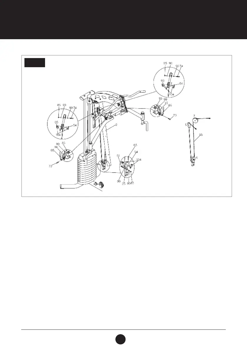
STEP 8:
Thread the Buttery Cable (65) through all the brackets of the unit.
Attach 1 end of the Buttery Cable (65) to the Right Adjustable Plate (16) using 1 Hex Bolt (3/8” x 1-1/ 4”) (73), 1
Washer (3/8”) (90) and 1 Locknut (3/8”) (85).
With the Buttery Cable (65) in the groove of the Pulley (54), install Pulley (5) with 2 Pulley Brackets (104) into
the Single Pulley Bracket (23) using 1 Hex Bolt (3/8” x 2”) (74), 2 Washers (3/8”) (90) and 1 Locknut (3/8”) (85).
With the Buttery Cable (65) in the groove of the Pulley (54), install Pulley( 6) with 2 Pulley Brackets (104) into
the top of the Intersect Pulley Bracket (25) using 1 Hex Bolt (3/8” x 2”) (74), 2 Washers (3/8”) (90) and 1 Locknut
(3/8”) (85).
With the Buttery Cable (65) in the groove of the Pulley( 54), install Pulley (7) with 2 Pulley Brackets (104) into
the Single Pulley Bracket (23) using 1 Hex Bolt (3/8” x 2”) (74), 2 Washers (3/8”) (90) and 1 Locknut (3/8”) (85).
Attach the other end of Buttery Cable (65) to the Left Adjustable Plate (15) using 1 Hex Bolt (3/8” x 1-1/4”) (73), 1
Washer (3/8”) (90) and 1 Locknut (3/8”) (85).
STEP 8