17
ASSEMBLY STEPS
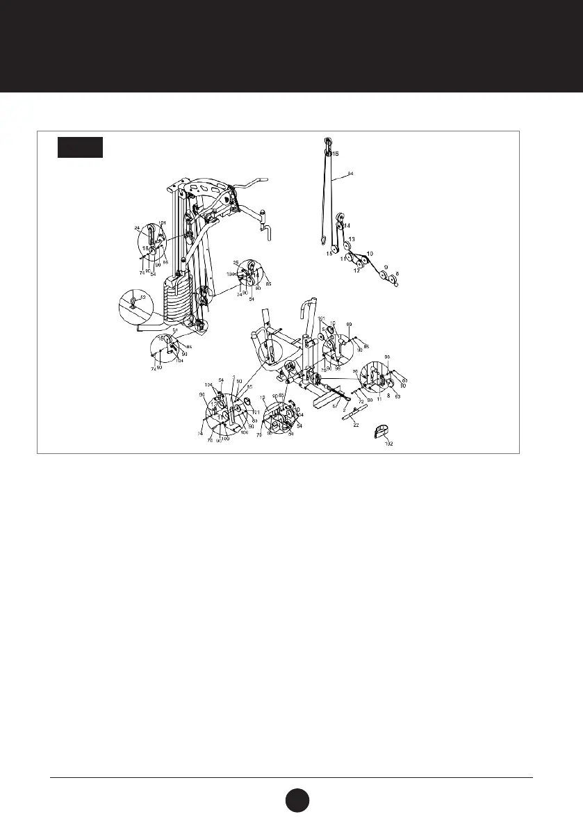
STEP 9:
Thread the Low Cable (64) through the brackets as shown.
With the Low Cable (64) in the groove of the Red Pulley (53), install Pulley (8) into the Leg Extension (11) using
1 Hex Bolt (3/8” x 2-1/2”) (72), 2 Washers (3/8”) (90) 2 Bushings (Ø13 x T 1.0 x 11 mm) (98), and 1 Locknut (3/8”)
(85).
With the Low Cable (64) in the groove of the Pulley (54), install Pulley (9) with 2 Pulley Guards (101) into the
Seat Support Post (10) using 1 Hex Bolt (3/8’’x 3”) (79), 2 Washers (3/8”) (90), 2 Bushings (Ø13 xT 1.0 x 17 mm)
(99) and 1 Locknut (3/8”) (85).
With the Low Cable (64) in the groove of the Pulley (54), install Pulleys (10, 12) with 4 Pulley Brackets (104) into
the brackets of the Bench Press Arm (13) using 1 Hex Bolt (3/8” x 3-3/8”) (70), 2 Washers (3/8”)(90) 1 Locknut
(3/8”) (85).
With the Low Cable (64) in the groove of the Pulley (54), install the Pulley (11) with 2 Pulley Guards (101) into
the slot of the Vertical Post (3) using 1 Hex Bolt (3/8” x 3-3/8”) (70), 2 Washers (3/8”) (90), 2 Bushings (Ø13 x T
1.0 x 22 mm) (100) and 1 Locknut (3/8”) (85).
With the Low Cable (64) in groove of the Pulley (54), install the Pulley (13) with 2 Pulley Brackets (104) into the
bracket of the Vertical Post (3) using 1 Hex Bolt (3/8” x 2”) (74), 2 Washers (3/8”) (90) and 1 Locknut (3/8”) (85).
STEP 9