18
ASSEMBLY STEPS
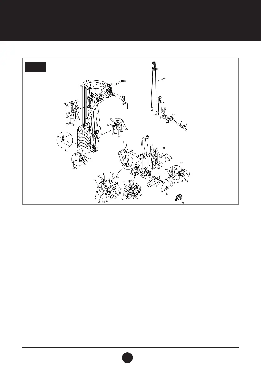
STEP 9:
With the Low Cable (64) in the groove of the Pulley( 54), installt he Pulley (14) with 2 Pulley Brackets (104) into
the Lower Intersect Pulley Bracket (25) using 1 Hex Bolt (3/8” x 2”) (74), 2 Washers (3/8”) (90) and 1 Locknut
(3/8”) (85).
With the Low Cable (64) in the groove of the Pulley (54), install the Pulley (15) with 2 Pulley Brackets (104) into
the bracket of the Main Base (1) using 1 Hex Bolt (3/8” x 2”) (74), 2 Washers (3/8”) (90) and 1 Locknut (3/8”)
(85).
With the Low Cable (64) in the groove of the Pulley (54), install the Pulley (16) with 2 Pulley Brackets (104) into
the Lower Pulley Bracket (24) using 1 Hex Bolt (3/8” x 2”) (74), 2 Washers (3/8”) (90) and 1 Locknut (3/8”) (85).
Connect 1 end of the Low Cable (64) to the Main Base (1) using 1 Hook (52).
Attach the Ball End of the Low Cable (64) to the Curl Bar (22) using the Chain (57) and 2 Hooks (52).
STEP 9