19
ASSEMBLY STEPS
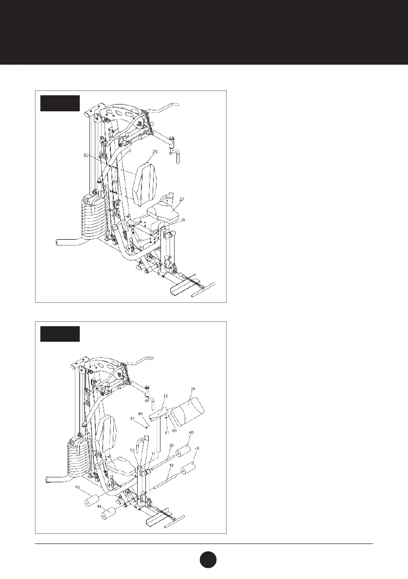
STEP 10:
Attach the Backrest Cushion (28) onto the
Vertical Post (3) using 2 Hex Bolts (M8 x
42 mm) (82) and 2 Washers (M8) (89).
Attach the Seat Cushion (27) onto the
Seat Cushion Support (9) using 4 Hex
Bolts (M8 x 16 mm) (81) and 4 Washers
(M5) (89).
STEP 11:
Attach the Arm Curl Cushion (26) onto the
Arm Curl Frame ( 12) using 2 Hex Bolts (M8
x 16 mm) (81) and 2 Washers (M8) (89).
Insert the Arm Curl Frame (12) into the
Seat Support Post (10) and secure with
the Pop Pin (50).
Insert the Foam Rod (20) through the
bushing of the Seat Support Post (10) and
slide 1 Foam Roll (46) onto each end.
Insert the Foam Rod (19) through the hole
of the Leg Extension (11) and slide 1 Foam
Roll (46) onto each end.
STEP 10
STEP 11