EN 9
clamp meter BE44
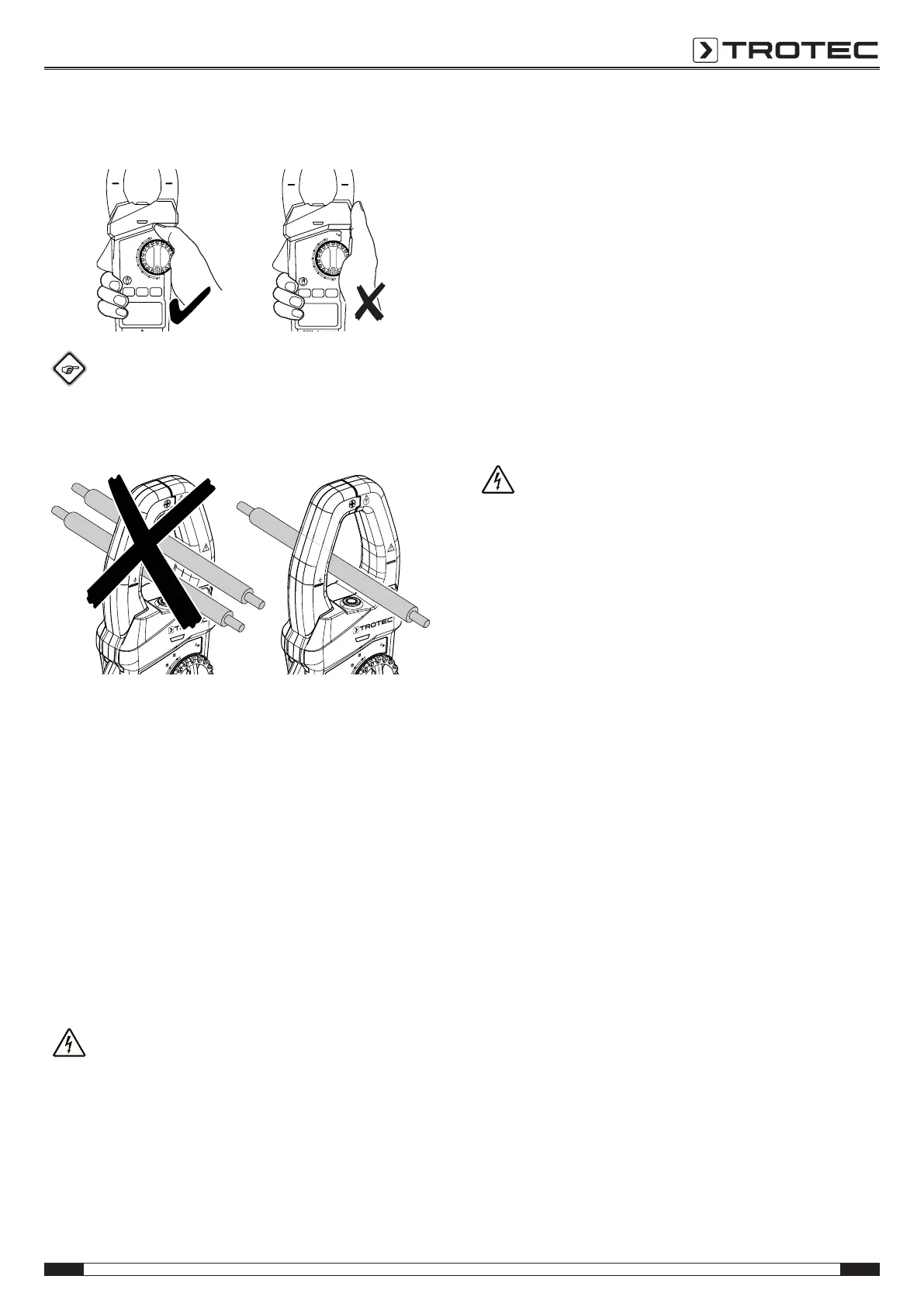
• When holding onto the clamp meter, make sure not to
reach behind the protection against contact(12):
Info
Only measure one conductor at a time to ensure an
unambiguous measurement result.
BE44
CAT III
1000V
1000A
MAX
NCV
Hz
60/600A
1000A
HOLD
Press 2 Sec
BE44
CAT III
1000V
1000A
MAX
NCV
Hz
60/600A
1000A
HOLD
Press 2 Sec
Please proceed as follows to measure the amperage of
alternating an direct currents:
1. Depending on the desired measuring range turn the rotary
switch(3) to the amperage 60/600A position(40) or to the
amperage 1000A position(41).
2. Repeatedly press the function button(35) to set the device
to the desired measurement of alternating or direct
current.
3. Squeeze the lever(9) to open the clamp(1) and insert the
conductor to be measured centrally in the clamp.
4. Use the clamping jaws' alignment marks on the clamp(1)
as guidance to properly centre the conductor.
ð The measured value will be displayed in the
measurement value display(24).
Resistance measurement
Warning of electrical voltage
Risk of electric shock and risk of injury when
measuring the resistance!
Make sure that the power of the electric circuit is
switched off and all capacitors are completely
discharged.
• When holding onto the measuring cables, make sure not to
reach behind the protection against contact(12).
Please proceed as follows to measure the resistance:
ü The circuit to be measured is switched off and
de-energized.
ü All capacitors are completely discharged.
1. Connect the black measuring cable(14) to the
COMconnection(7) and the red measuring cable(13) to
the Input connection(6).
2. Turn the rotary switch(3) to the resistance position(38).
3. Repeatedly press the function button(34) until a unit for
the resistance is indicated in the respective section of the
display(22).
4. Tap the desired measuring points of the electric circuit
with the test probes(11) at the measuring cables.
ð The measured value will be displayed in the
measurement value display(24).
Continuity testing
Warning of electrical voltage
Risk of electric shock and risk of injury when
checking the continuity!
Make sure that the power of the electric circuit is
switched off and all capacitors are completely
discharged.
• When holding onto the measuring cables, make sure not to
reach behind the protection against contact(12).
• Do not use the device if the wear indicator in the jaw
opening is no longer visible.
Please proceed as follows to check the continuity of the circuit
to be tested:
ü The electrical circuit is deactivated.
ü All capacitors are completely discharged.
1. Connect the black measuring cable(14) to the
COMconnection(7) and the red measuring cable(13) to
the Input connection(6).
2. Turn the rotary switch(3) to the continuity position(38).
3. Repeatedly press the function button(34) until the icon for
continuity testing is displayed via the continuity check
indication(19).
4. Tap the desired measuring points of the electric circuit
with the test probes(11) at the measuring cables.
ð The device will emit an acoustic signal if the measured
resistance amounts to less than 20Ω.
ð The device will not emit an acoustic signal if the
measured resistance amounts to more than 150Ω.
ð The device may emit an acoustic signal if the measured
resistance ranges between 20Ω and 150Ω.