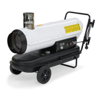
EN Operating manual – Oil heater IDE 20 / IDE 30 / IDE 50 / IDE 60 / IDE 80 5
Wheel assembly
The device is delivered almost ready for operation. For start-up,
only the tubular frame and the wheels must be assembled.
Proceed as follows:
• Guide the wheel axle (H) into the corresponding mount of the
lower tubular frame (B).
• Slide the washer (G) onto the axle and mount both wheels (E)
onto the axle (H).
• Secure them with the cover caps (E).
• Position the device (I) on the lower tubular frame and insert
the supplied screws (C) through the openings for the tubular
frame/tank assembly.
• Mount the upper tubular frame (A) onto the tank and fasten
the tubular frames with the supplied nuts.
• Finally check all screws and clamp connections for tight fit.
Assembly of the exhaust line
Note that this device must not be put into operation
unless there is an exhaust line assembled at the
chimney connection!
Assembly of the chimney adapter
For outdoor use and for use in partly closed, well-ventilated
rooms without an exhaust system, it is necessary to mount a
simple chimney adapter (B) to the chimney connection (C).
Observe the following:
• The adapter (B) must have a minimum length of 1 m.
• Bends and elbows in this line are prohibited.
• If the device is used outdoors, a weather protection (A) must
be mounted to the end.
Assembly of a closed exhaust line
If the device is used in closed rooms and the combustion gases
are discharged via a chimney, a fresh air supply of
approx. 80 m³/h (air inlet opening approx. 0.5 m²) must be
ensured.
Make sure that in every operating and weather
condition a vacuum of > 0.1 mbar is created in the
exhaust line. This vacuum guarantees a safe
discharge of exhaust gases from the room. The
exhaust line must be installed upward. There must be
no bends or elbows in the first 3 metres of the
exhaust line!
Below are some examples of good and bad exhaust gas
discharge:
Final assembly
>3m
>5m
>3m
>6m
>3m
max.10m
10%
 Loading...