EN 16
Operating manual – dehumidifier TTK 28 E
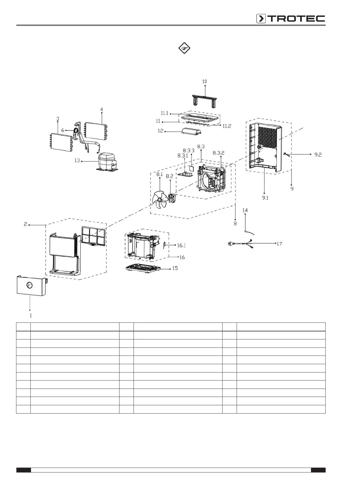
Spare parts drawing and list
Info
The position numbers of the spare parts differ from
those describing the positions of other parts mentioned
in this operating manual.
No. Spare part No. Spare part No. Spare part
1 Water Tank Assembly 8.3.2 Volute shell 13 Fixed Speed Reciprocating Compressor
2 Front panel 8.3.3 Humidity Sensor Board Subassembly 14 Temperature Sensor
3 Evaporator assembly Gas valve assembly 9 Rear panel assembly 15 Chassis assembly
4 Condenser Assembly 9.1 Rear panel 16 Partition board assembly
6 Capillary Assembly 9.2 Drain Stopper 16.1 Micro Switch
8 Volute shell assembly 10 Handle 17 Power Supply Cable Subassembly
8.1 Axial fan 11 Top cover assembly wheel bearing
8.2 Shaded Pole Motor 11.1 Top cover wheel
8.3 Electronic control box assembly 11.2 Display box assembly plastic drain pipe
8.3.1 Main control board assembly 12 Fire-proof cover, E-part box Subassembly packing box