15 EN
Operating manual – dehumidifier TTK 28 E
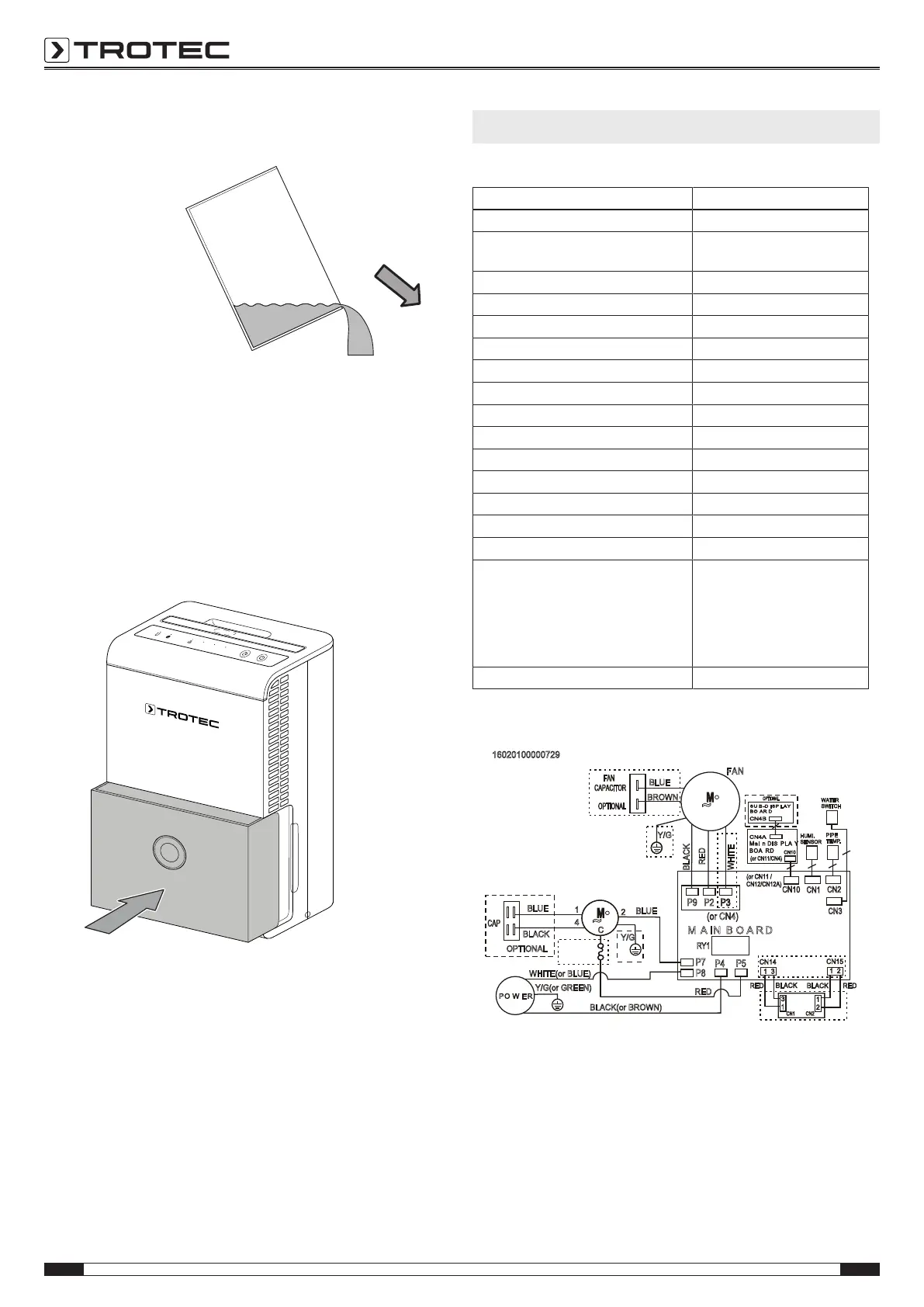
2. Empty the condensation tank over a drain or sink.
3. Rinse the tank with clear water. Clean the tank regularly
using a mild cleaning agent (no detergent!).
4. Refit the condensation tank into the device.
Make sure not to damage the float when inserting or
removing the condensation tank.
In doing so, make sure that the float is positioned correctly.
In doing so, make sure that the condensation tank is
inserted correctly, for otherwise the device cannot be
switched back on.
Activities required after maintenance
If you want to continue using the device:
• Leave the device to rest for 12-24hours, so the
refrigerant can accumulate within the compressor. Wait
12-24hours before switching the device back on! Acting
contrary might lead to compressor damage and a
malfunctioning device. If so, any warranty claims will be
voided.
• Reconnect the device to the mains.
If you do not intend to use the device for a considerable time:
• Store the device according to the Storage chapter.
Technical annex
Technical data
Model TTK28E
Max. dehumidification performance 10 l / 24 h
Dehumidification performance @ 30°C
and 80%RH
8.56l/h
Air flow rate 100 m
3
/h
Ambient temperature 5°C to 35°C
Operating range 35 % to 85 % RH
Power supply 1/N/PE ~ 230 V/ 50 Hz
Power consumption 0.27 kW
Nominal current 1.6 A
Refrigerant R134a
Amount of refrigerant 70 g
GWP factor 1430
CO
2
equivalent 0.1t
Condensation tank capacity 2 l
Sound pressure level (1m distance) 43 dB(A)
Dimensions (length x width x height) 237 x 300 x 410 mm
Minimum distance to walls and other
objects
A: top:
B: rear:
C: side:
D: front:
40 cm
20 cm
20 cm
20 cm
Weight 11.5 kg
Wiring diagram
16020100000729
Mai n DIS PLA Y
BOA RD
M A IN B O A R D
PO W E R
CN10
CN10
P8
(or CN4)
BLACK(or BROWN)
RED
WHITE(or BLUE)
WHITE
RED
Y/G
Y/G(or GREEN)
RY1
BLACK
BLUE
BROWN
FAN
CAPACITOR
Y/G
1
C
4
•
~
FAN
P9
P3
OverLoad
Protector
P3P2
P7
(or CN11 /
CN12/CN12A)
(or CN11/CN4)
OPTIONAL
BLUE
BLACK
OPTIONAL
CAP
2
BLUE
SU B-D ISP LAY
BO A R D
CN4B
CN4A
HUMI.
SENSOR
•
~
OPTIONAL
CN1
PIPE
TEMP.
CN2
WATER
SWITCH
CN3
DC POWER
BOARD
CN1
CN2
CN14
CN15
RED
1 3
BLACK
1 2
RED
BLACK
3
1
1
2
P4
P5